2.1 Spindle drives
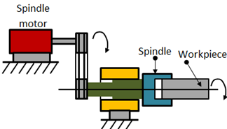
Fig. 4.1.1 Schematic of a spindle drive
The spindle drives are used to provide angular motion to the workpiece or a cutting tool. Figure 4.1.1 shows the components of a spindle drive. These drives are essentially required to maintain the speed accurately within a power band which will enable machining of a variety of materials with variations in material hardness. The speed ranges can be from 10 to 20,000 rpm. The machine tools mostly employ DC spindle drives. But as of late, the AC drives are preferred to DC drives due to the advent of microprocessor-based AC frequency inverter. High overload capacity is also needed for unintended overloads on the spindle due to an inappropriate feed. It is desirous to have a compact drive with highly smooth operation.
2.2 Feed Drives
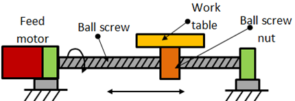
Fig. 4.1.2 Typical feed drive
These are used to drive the slide or a table. Figure 4.1.2 shows various elements of a feed drive. The requirements of an ideal feed drive are as follows.
- The feed motor needs to operate with constant torque characteristics to overcome friction and working forces.
- The drive speed should be extremely variable with a speed range of about 1: 20000, which means it should have a maximum speed of around 2000 rpm and at a minimum speed of 0.1 rpm.
- The feed motor must run smoothly.
- The drive should have extremely small positioning resolution.
- Other requirements include high torque to weight ratio, low rotor inertia and quick response in case of contouring operation where several feed drives have to work simultaneously.
Variable speed DC drives are used as feed drives in CNC machine tools. However now-a-days AC feed drives are being used.