Displacement sensors are basically used for the measurement of movement of an object. Position sensors are employed to determine the position of an object in relation to some reference point.
Proximity sensors are a type of position sensor and are used to trace when an object has moved with in particular critical distance of a transducer.
Displacement sensors
1. Potentiometer Sensors
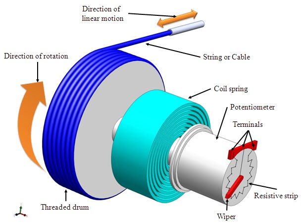
Figure 2.2.1 Schematic of a potentiometer sensor for measurement of linear displacement
Figure 2.2.1 shows the construction of a rotary type potentiometer sensor employed to measure the linear displacement. The potentiometer can be of linear or angular type. It works on the principle of conversion of mechanical displacement into an electrical signal. The sensor has a resistive element and a sliding contact (wiper). The slider moves along this conductive body, acting as a movable electric contact.
The object of whose displacement is to be measured is connected to the slider by using
- a rotating shaft (for angular displacement)
- a moving rod (for linear displacement)
- a cable that is kept stretched during operation
The resistive element is a wire wound track or conductive plastic. The track comprises of large number of closely packed turns of a resistive wire. Conductive plastic is made up of plastic resin embedded with the carbon powder. Wire wound track has a resolution of the order of ± 0.01 % while the conductive plastic may have the resolution of about 0.1 µm.
During the sensing operation, a voltage VS is applied across the resistive element. A voltage divider circuit is formed when slider comes into contact with the wire. The output voltage (VA) is measured as shown in the figure 2.2.2. The output voltage is proportional to the displacement of the slider over the wire. Then the output parameter displacement is calibrated against the output voltage VA.