Step 4: Locus of end B in the top view
It is evident from figure 2, that when the line AB is swept around about the end A by one complete rotation, keeping f the inclination of the line with the VP constant, the end B will always be at the same distance in front of VP and the locus of the end B will be a circle which appears in the top view as a line, parallel to XY, passing through b.
As long as the line is inclined at φ to VP, whatever may be the position of the line (i.e., whatever may be the inclination of the line with HP), the length of the front view will always be equal to a'b2' and in the top view the projection of the end B lies on the locus line passing through b2.
Thus a΄b2΄ the front view of the line when it is inclined at f to VP and parallel to HP, will be equal to a'b' and also b, the projection of the end B in the top view lies on the locus line passing through b2.
Step 5: To obtain the top and front views of AB
From the above two cases of rotation it can be said that
(i)the length of the line AB in top and front views will be equal to ab1 and a'b2' respectively and
(ii) The projections of the end B, (i.e., b and b‘) should lie along the locus line passing through b2 and b1΄ respectively.
With center a, and radius ab2 draw an arc to intersect the locus line through b2 at b. Connect ab the top view of the line AB.
Similarly with center a', and radius a'b2' draw an arc to intersect the locus line through b1' at b΄. Connect a'b' the front view of the line AB.
Orthographic projections
As the location of one of the end points (i.e. A) with respect to HP and VP, is given, mark a anda΄, the top and the front views of point A.
If the line AB is assumed to be made parallel to VP and inclined at θ to HP. The front view of the line will be equal to the true length and true inclination of the line with HP. Draw a'b1' passing through a' at θ to XY line and equal to the true length of AB. a'b1' is projected down to get ab1, the top view parallel to the XY line. This is illustrated in figure 3.
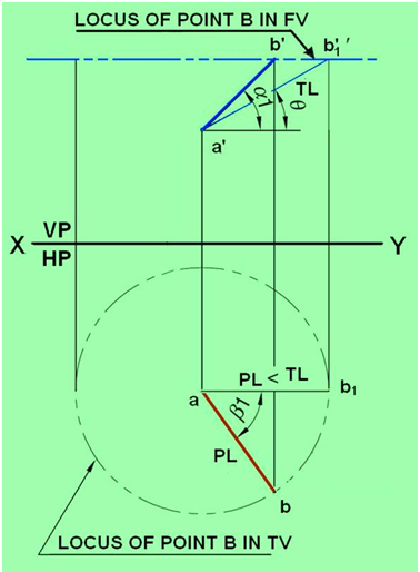
Figure 3. Illustrates the true length and true inclination of the line when it is made parallel to VP.
Now the line AB is assumed to be made parallel to HP and inclined at φ to VP. This is shown in figure 4. The top view of the line will be equal to the true length of the line and also φ, the inclination of the line with VP is seen in the top view. For this, draw ab2 passing through a and incline at φ to the XY line. The length ab2 is equal to the true length of AB. The end points a and b2 are projected on to a line parallel to XY line and passing through a’ to get a'b2' which is the front view of the line when it is parallel to HP and inclined to VP. Draw the horizontal locus lines through b2, and b1'. With center a and radius ab1, draw an arc to cut the locus line drawn through b2 at b. Connect ab, the top view of the line AB. With center a' and radius a'b2΄, draw an arc to cut the locus line drawn through b1' at b'. Connect a'b', the front view of the line AB. Orthographic projections of line AB inclined to both VP and HP, illustrating the projected length, true lengths apparent inclinations and true inclinations are shown in figure 5.