Point in the Second quadrant
Point P is 30 mm above HP, 50 mm behind VP and 45 mm in front of left PP. Since point P is located behind VP, the VP is assumed transparent. The position of the point w.r.t the three planes are shown in Figure 1. The direction of viewing are shown by arrows. After projecting the point on to the three planes, the HP and PP are rotated such that they lie along the VP. The direction of rotation of the HP and PP is shown in figure 2. As shown in figure 3, after rotation of the PP and HP, it is found that the VP and HP is overlapping. The multiview drawing for the point P lying in the second quadrant is shown in figure 4. Though for the projection of a single point, this may not be a problem, the multiview drawing of solids, where a number of lines are to be drawn, will be very complicated. Hence second angle projection technic is not followed anywhere for engineering drawing.
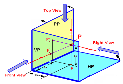
Figure 1. The projection of point P on to the three projection planes.
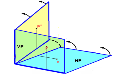
Figure 2. The direction of rotation of HP.
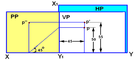
Figure 3. The projection of point P after complete rotation of the HP and PP.