Figure 4 shows the planes and the position of the points when the planes are partially rotated. The arrows indicate the direction of rotation of the planes. The three views after complete rotation of the planes is shown in figure 2.

Figure 4. Projection of the point “P” on to the three projection planes after the planes are partially rotated.
The procedure of drawing the three views of the point “P” is shown in figure-4.
- Draw a thin horizontal line, XY, to represent the line of intersection of HP and VP.
- Draw X1Y1 line to represent the line of intersection of VP and PP.
- Draw the Top View (p).
- Draw the projector line
- Draw the Front View (p΄) .
- To project the right view on the left PP, draw a horizontal projector through p to intersect the 45 degree line at m. Through m draw a vertical projector to intersect the horizontal projector drawn through p΄ at p΄΄.
- p΄΄ is the right view of point P
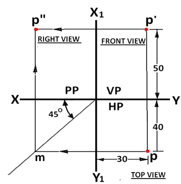
Figure 5 First angle multi-view drawing of the point “P”