Projection Methods
Universally either the 1st angle projection or the third angle projection methods is followed for obtaining engineering drawings. The principal projection planes and quadrants used to create drawings are shown in figure 16. The object can be considered to be in any of the four quadrant.
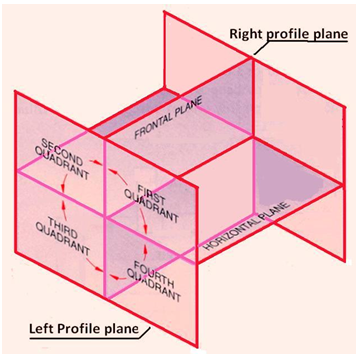
Figure 16. The principal projection planes and quadrants for creation of drawings.
First Angle Projection
In this the object in assumed to be positioned in the first quadrant and is shown in figure 17 The object is assumed to be positioned in between the projection planes and the observer. The views are obtained by projecting the images on the respective planes. Note that the right hand side view is projected on the plane placed at the left of the object. After projecting on to the respective planes, the bottom plane and left plane is unfolded on to the front view plane. i.e. the left plane is unfolded towards the left side to obtain the Right hand side view on the left side of the Front view and aligned with the Front view. The bottom plane is unfolded towards the bottom to obtain the Top view below the Front view and aligned with the Front View.
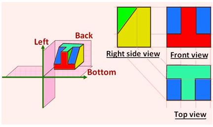
Figure 17. Illustrating the views obtained using first angle projection technique.