| Let us now understand the details of the technique mentioned earlier. Firstly we choose to place balancing or correcting masses on the shaft (rotating along with the shaft) to counter-act the unbalance forces. We understand that this is to be done on the rotor on site, perhaps during a maintenance period. From the point of view of accessibility, we therefore choose the balancing masses to be kept near the bearings.
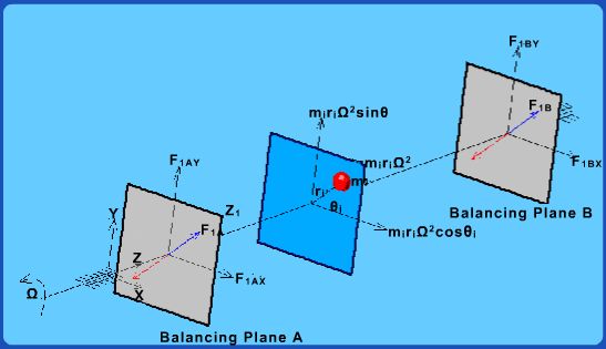
Figure 2.3.1 Two plane balancing technique
The calculations proceed as shown in Fig. 2.3.1. For an unbalance mass mi situated at an angular location  in a plane at an axial distance in a plane at an axial distance  from the left end bearing and rotating at a radius from the left end bearing and rotating at a radius  as shown in the figure, the unbalance force is as shown in the figure, the unbalance force is
 . It is resolved into X and Y components as shown in the figure. These forces are represented by EQUIVALENT FORCES in the balancing planes ( shown in blue . It is resolved into X and Y components as shown in the figure. These forces are represented by EQUIVALENT FORCES in the balancing planes ( shown in blue  ). These forces can be readily calculated (based on calculations similar to those involved in finding support reactions for a simply supported beam). In order to counterbalance this force, we need to place a balancing mass ). These forces can be readily calculated (based on calculations similar to those involved in finding support reactions for a simply supported beam). In order to counterbalance this force, we need to place a balancing mass  at a radius at a radius  in the balancing plane such that it creates an equal and opposite force ( shown in red ). in the balancing plane such that it creates an equal and opposite force ( shown in red ). |