Section I: Power-Angle Relationship
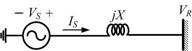
The power-angle relationship has been discussed in Section 2.4.3. In this section we shall consider this relation for a lumped parameter lossless transmission line. Consider the single-machine-infinite-bus (SMIB) system shown in Fig. 9.1. In this the reactance X includes the reactance of the transmission line and the synchronous reactance or the transient reactance of the generator. The sending end voltage is then the internal emf of the generator. Let the sending and receiving end voltages be given by
 |
(9.1) |
Fig. 9.1 An SMIB system.
We then have
 |
(9.2) |
The sending end real power and reactive power are then given by
This is simplified to
 |
(9.3) |
Since the line is loss less, the real power dispatched from the sending end is equal to the real power received at the receiving end. We can therefore write
 |
(9.4) |
where Pmax = V1 V2 / X is the maximum power that can be transmitted over the transmission line. The power-angle curve is shown in Fig. 9.2. From this figure we can see that for a given power P0 . There are two possible values of the angle δ - δ0 and δmax . The angles are given by
 |
(9.5) |
Example 9.1 |