Line-to-Line Fault
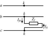
The faulted segment for an L-L fault is shown in Fig. 8.5 where it is assumed that the fault has occurred at node k of the network. In this the phases b and c got shorted through the impedance Zf . Since the system is unloaded before the occurrence of the fault we have
 |
(8.8) |
Fig. 8.5 Representation of L-L fault.
Also since phases b and c are shorted we have
 |
(8.9) |
Therefore from (8.8) and (8.9) we have
 |
(8.10) |
We can then summarize from (8.10)
 |
(8.11) |
Therefore no zero sequence current is injected into the network at bus k and hence the zero sequence remains a dead network for an L-L fault. The positive and negative sequence currents are negative of each other.
Now from Fig. 8.5 we get the following expression for the voltage at the faulted point
 |
(8.12) |
Again
 |
(8.13) |
Moreover since I fa0 = I fb0 = 0 and I fa1 = - I fb2 , we can write
 |
(8.14) |
Therefore combining (8.12) - (8.14) we get
 |
(8.15) |
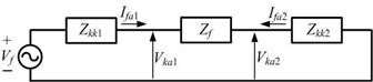
Equations (8.12) and (8.15) indicate that the positive and negative sequence networks are in parallel. The sequence network is then as shown in Fig. 8.6. From this network we get
 |
(8.16) |
Fig. 8.6 Thevenin equivalent of an LL fault.
Example 8.2
|