Example 7.5
Let us consider the network shown in Fig 7.17 which is essentially the same as that discussed in Example 1.2. The values of the various reactances are not important here and hence are not given in this figure. However various points of the circuit are denoted by the letters A to G . This has been done to identify the impedances of various circuit elements.
For example, the leakage reactance of the transformer T1 is placed between the points A and B and that of transformer T2 is placed between D and E .
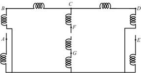
The positive sequence network is shown in Fig. 7.18. This is essentially same as that shown in Fig. 1.24. The negative sequence diagram, shown in Fig. 7.19, is almost identical to the positive sequence diagram except that the voltage sources are absent in this circuit. The zero sequence network is shown in Fig. 7.20. The neutral point of generator G1 is grounded. Hence a path from point A to the ground is provided through the zero sequence reactance of the generator. The primary side of the transformer T1 is Δ -connected and hence there is discontinuity in the circuit after point A . Similar connections are also made for generator G2 and transformer T2 . The transmission line impedances are placed between the points B - C , C - D and C - F . The secondary side of transformer T3 is ungrounded and hence there is a break in the circuit after the point F . However the primary side of T3 is grounded and so is the neutral point of generator G3 . Hence the zero sequence components of these two apparatus are connected to the ground.
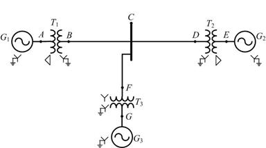 |
Fig. 7.17 Single-line diagram of a 3-machine power system.
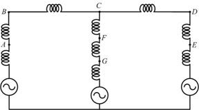
Fig. 7.18 Positive sequence network of the power system of Fig. 7.17.
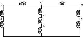
Fig. 7.19 Negative sequence network of the power system of Fig. 7.17.
Fig. 7.20 Zero sequence network of the power system of Fig. 7.17.
|