Fault in an AC Circuit
Now consider the single-phase circuit of Fig. 6.5 where Vs = 240 V (rms), the system frequency is 50 Hz, R = 0.864 Ω, L = 11 mH ( ωL = 3.46 Ω ) and the load is R-L comprising of an 8.64 W resistor and a 49.5 mH inductor ( ωL = 15.55Ω ). With the system operating in the steady state, the switch S is suddenly closed creating a short circuit. The current (i ) waveform is shown in Fig. 6.6. The current phasor before the short circuit occurs is
 A A
This means that the pre-fault current has a peak value of 15.97 A.
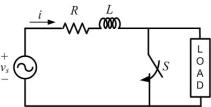
Fig. 6.5 A single-phase circuit in which a source supplies a load through a source impedance.
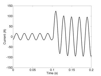
Fig 6.6 The current waveform of the circuit of Fig 6.5 before and after the closing of the switch S
Once the fault occurs and the system is allowed to reach the steady state, the current phasor is given by
This current has a peak value of 95.28 A. However it can be seen that the current rises suddenly and the first peak following the fault is 124 A which is about 30% higher than the post-fault steady-state value. Also note that the peak value of the current will vary with the instant of the occurrence of the fault. However the peak value of the current is nearly 8 times the pre-fault current value in this case. In general, depending on the ratio of source and load impedances, the faulted current may shoot up anywhere between 10 and 20 times the pre-fault current.
|