Section II: Automatic Generation Control
Automatic Generation Control
Electric power is generated by converting mechanical energy into electrical energy. The rotor mass, which contains turbine and generator units, stores kinetic energy due to its rotation. This stored kinetic energy accounts for sudden increase in the load. Let us denote the mechanical torque input by Tm and the output electrical torque by Te . Neglecting the rotational losses, a generator unit is said to be operating in the steady state at a constant speed when the difference between these two elements of torque is zero. In this case we say that the accelerating torque
 |
(5.20) |
is zero.
When the electric power demand increases suddenly, the electric torque increases. However, without any feedback mechanism to alter the mechanical torque, Tm remains constant. Therefore the accelerating torque given by (5.20) becomes negative causing a deceleration of the rotor mass. As the rotor decelerates, kinetic energy is released to supply the increase in the load. Also note that during this time, the system frequency, which is proportional to the rotor speed, also decreases. We can thus infer that any deviation in the frequency for its nominal value of 50 or 60 Hz is indicative of the imbalance between Tm and Te. The frequency drops when Tm < Te and rises when Tm > Te .
The steady state power-frequency relation is shown in Fig. 5.3. In this figure the slope of the ΔPref line is negative and is given by
 |
(5.21) |
where R is called the regulating constant . From this figure we can write the steady state power frequency relation as
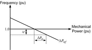
Fig. 5.3 A typical steady-state power-frequency curve.
 |
(5.22) |
Suppose an interconnected power system contains N turbine-generator units. Then the steady-state power-frequency relation is given by the summation of (5.22) for each of these units as
 |
(5.23) |
In the above equation, ΔPm is the total change in turbine-generator mechanical power and ΔPref is the total change in the reference power settings in the power system. Also note that since all the generators are supposed to work in synchronism, the change is frequency of each of the units is the same and is denoted by Δf. Then the frequency response characteristics is defined as
 |
(5.24) |
We can therefore modify (5.23) as
 |
(5.25) |
Example 5.5 |