| Cascaded transformers
|
- Cascading a number of single identical units makes transportation, production and erection simpler.
- The cascading principle is illustrated with the basic scheme shown in Fig. 24.3 below in which it can be seen that output of a stage transformer becomes input for the next stage.
|
| |
|
Fig 24.3 Three Transformers in cascade
(1) Primary windings,
(2)
Secondary, HV, windings,
(3) Tertiary/ excitation windings (4) Core |
| |
- The HV supply is connected to the primary winding "1" of transformer I, designed for a HV output of V. The other two transformers too are connected in the same fashion.
- The excitation winding "3" of Transformer I supplies the primary voltage for the second transformer unit II; both windings are dimensioned for the same low voltage, and the potential gain is fixed to the same value V.
- The HV or secondary windings "2" of both units are connected in series, so that a voltage of 2 V is produced at the output of 2nd unit. The unit III is added in the same way.
- The tanks or vessels containing the active parts (core and windings) are indicated by dashed lines.
- For a metal tank construction and the HV windings shown in this basic scheme, the core and the tank of each unit would acquire the HV level of the previous unit as indicated . Only the tank of transformer I is earthed.
- The tanks of transformers II and III are at high potentials, namely V and 2 V above earth, and must therefore be suitably insulated, hence raised above the ground on solid post insulators.
- Through HV bushings the leads from the excitation windings "3", as well as the tapings of the HV windings "2", are brought to the next transformer.
|
| |
| For voltages higher than about 600 kV , the cascade of such transformers is a big advantage. The weight and the size of the testing set is sub-divided into single units of smaller size and lower weight. The transportation and erection of the test set in cascade becomes simpler. However, there is a disadvantage that the primary windings of the lower stages are more heavily loaded with higher current in such sets. |
|
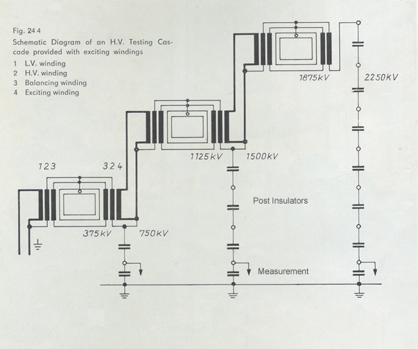
Fig. 24.4 Schematic of an ac test set circuit in cascade |
| |
There are several methods of designing the cascade test sets. In Fig. 24.4 schematic diagram of another power frequency test set cascade of 3 x 750 = 2250 kV rating is shown. This circuit has a third winding, known as "Balancing Winding''. These windings are designed to acquire the intermediate potentials between two stages. In this circuit, the transformers of the upper stages have their excitation windings arranged over the HV windings of the transformers of the lower potential. Fig. 24.5 shows a photograph of this test set installed in open air.
|
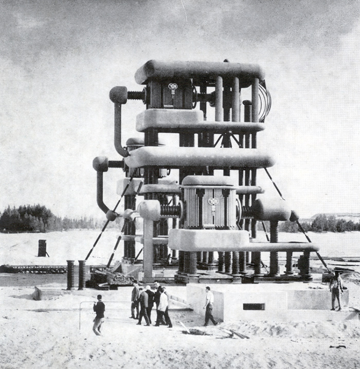 |
Fig. 24.5 Photograph of an ac test set of 2250 kV, 2250 kVA installed outdoors |
| People walking on the ground in this photograph gives an idea of the huge size of the test set. |
| |
|