Introduction
The topics covered in this chapter are as follows:
- • The drive train configuration
• Various types of vehicle power plants
• The need of gearbox in a vehicle
• The mathematical model of vehicle performance
Drive train Configuration
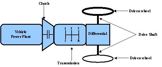
An automotive drive train is shown in Figure 1 . It consists of:
- • a power plant
• a clutch in a manual transmission or a torque converter in automatic transmission
• a gear box
• final drive
• differential shaft
• driven wheels
The torque and rotating speed from the output shaft of the power plant are transmitted to the driven wheels through the clutch or torque converter, gearbox, final drive, differential and drive shaft.
The clutch is used in manual transmission to couple or decouple the gearbox to the power plant. The torque converter in an automatic transmission is hydrodynamic device, functioning as the clutch in manual transmission with a continuously variable gear ratio.
The gearbox supplies a few gear ratios from its input shaft to its output shaft for the power plant torque-speed profile to match the requirements of the load. The final drive is usually a pair of gears that supply a further speed reduction and distribute the torque to each wheel through the differential.
|
Vehicle power plant
There are two limiting factors to the maximum tractive effort of the vehicle:
- • Maximum tractive effort that the tire-ground contact can support
• Tractive effort that the maximum torque of the power plant can produce with the given driveline gear ratios.
The smaller of these factors will determine the performance potential of the vehicle. Usually it is the second factor that limits the vehicles performance.