1 Digital Control System
A digital control system model can be viewed from different perspectives including control algorithm, computer program, conversion between analog and digital domains, system performance etc. One of the most important aspects is the sampling process level.
In continuous time control systems, all the system variables are continuous signals. Whether the system is linear or nonlinear, all variables are continuously present and therefore known (available) at all times. A typical continuous time control system is shown in Figure 1.
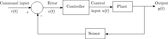
Figure 1: A typical closed loop continuous time control system
In a digital control system, the control algorithm is implemented in a digital computer. The error signal is discretized and fed to the computer by using an A/D (analog to digital) converter. The controller output is again a discrete signal which is applied to the plant after using a D/A (digital to analog) converter. General block diagram of a digital control system is shown in Figure 2.
![]() is sampled at intervals of
is sampled at intervals of ![]() . In the context of control and communication, sampling is a process by which a continuous time signal is converted into a sequence of numbers at discrete time intervals. It is a fundamental property of digital control systems because of the discrete nature of operation of digital computers.
. In the context of control and communication, sampling is a process by which a continuous time signal is converted into a sequence of numbers at discrete time intervals. It is a fundamental property of digital control systems because of the discrete nature of operation of digital computers.
Figure 3 shows the structure and operation of a finite pulse width sampler, where (a) represents the basic block diagram and (b) illustrates the function of the same. ![]() is the sampling period and
is the sampling period and ![]() is the sample duration.
is the sample duration.