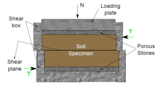
Fig. 6.3. Free-body diagram of direct shear apparatus
A vertical normal load (N) is applied to the specimen and shear load (T) is applied on horizontal plane of one half either at constant strain or constant stress condition. The applied shear makes the two halves to move relatively along the pre-determined failure plane under the vertical normal load. The displacements in horizontal and vertical directions are measured, during the test, using dial gauges mounted on the sample along vertical and horizontal directions. The test is stopped when either peak strength or maximum displacement is observed. The tests are conducted using similar samples under different vertical normal loads. The shear strength parameters are obtained from the failure envelope which can be obtained by plotting the shear stresses at failure against the normal stress for each test as shown in Fig. 6.4.
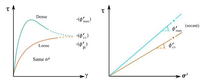
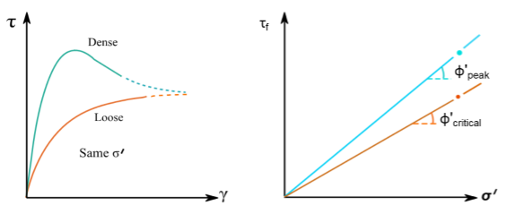
Fig. 6.4. Shear envelopes obtained by direct shear tests (a) shear stress vs. shear strain plot (b) shear stress at failure vs. normal stress
Triaxial test is a most widely used test in the laboratory for measuring the shear strength of soils. The drainage can be controlled advantageously during shearing in this test. A cylindrical sample is contained in a Perspex cell as shown in Fig. 6.5a-b. Connections to the soil sample from the external water reservoir are established to control the pore water pressure in the soils and to provide free drainage. An all-round water pressure, ![]() , is initially applied by pressurizing the water in the cell. Consolidation is allowed during this stage, if required, depending on the test condition.
, is initially applied by pressurizing the water in the cell. Consolidation is allowed during this stage, if required, depending on the test condition.