Flow Nets
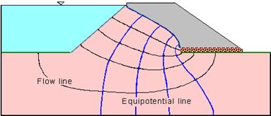
Graphical form of solutions to Laplace equation for two-dimensional seepage can be presented as flow nets. Two orthogonal sets of curves form a flow net:
- Equipotential lines connecting points of equal total head h
- Flow lines indicating the direction of seepage down a hydraulic gradient
Two flow lines can never meet and similarly, two equipotential lines can never meet. The space between two adjacent flow lines is known as a flow channel, and the figure formed on the flownet between any two adjacent flow lines and two adjacent equipotential lines is referred to as a field. Seepage through an embankment dam is shown.
Calculation of flow in a channel
If standpipe piezometers were inserted into the ground with their tips on a single equipotential line, then the water would rise to the same level in each standpipe. The pore pressures would be different because of their different elevations.There can be no flow along an equipotential line as there is no hydraulic gradient.
Consider a field of length L within a flow channel. There is a fall of total head Dh. The average hydraulic gradient is
As the flow lines are b apart and considering unit length perpendicuar to field, the flow rate is
![]()
There is an advantage in sketching flow nets in the form of curvilinear 'squares' so that a circle can be insrcibed within each four-sided figure bounded by two equipotential lines and two flow lines.
In such a square, b = L , and the flow rate is obtained as Dq = k.Dh
Thus the flow rate through such a flow channel is the permeability k multiplied by the uniform interval Dh between adjacent equipotential lines.
Calculation of total flow
For a complete problem, the flow net can be drawn with the overall head drop h divided into Nd so that Dh = h / Nd.
If Nf is the no. of flow channels,
then the total flow rate is
![]()