| |
| | |
|
Emerging or non-traditional techniques are based on using ``point'' vehicle
detection equipment, such as inductance loop detectors or video cameras.
Travel time estimation algorithms have been developed based upon measurable
point parameters such as volume, lane occupancy, or vehicle headways.
Image matching algorithms are used to match vehicle images or signatures
captured at two consecutive observation points.
Following are some of the methods used in emerging techniques [16].
Estimates average travel time by spot speeds, applied for short roadway segments
between detection devices.
It is more suitable for low accuracy application.
The most accurate method to measure vehicle speed with loop detectors is to
place two detectors in series, which is referred to as ``speed trap'' or ``loop
trap''.
The accuracy of inductance loop speed traps is dependent upon the trap length,
inductance loop wire type, and consistency in design.
Many inductance loop detectors are single loops; primary application is to
collect vehicle counts and lane occupancy.
Many research attempts have been made to utilize speed-flow relationships to
estimate vehicle speeds from single loop detectors.
The following 1 and 2
equations have been used to estimate spot speeds from single loop detectors
[16].
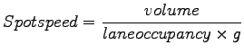 |
(1) |
where,
 = speed correction factor (based upon assumed vehicle length, detector
configuration, and traffic conditions). = speed correction factor (based upon assumed vehicle length, detector
configuration, and traffic conditions).
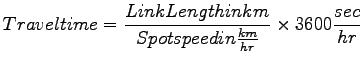 |
(2) |
Calculates travel time by matching unique vehicle signatures between sequential
observation points.
These methods can utilize a number of point detectors such as inductance loop
detectors, weigh-in motion sensors, video cameras, and laser scanning detectors.
Vehicle signatures between two consecutive locations to provide a link based
travel time and speed.
It provides alternative to ITS probe vehicle based on travel time measurement,
in which a probe vehicle is identified and matched between two locations using a
unique identification number.
Vehicle signature matching had been investigated using a number of different
point detection devices, mostly with inductance loop detectors.
Several algorithms are available to capture vehicle signatures from a loop
detector frequency detuning curve.
Different types and classes of vehicles provide different types of signatures.
The unique features of a vehicle signature are then compared to signatures
within a given time frame at a downstream location.
The signature is matched when a large number of feature correlations have been
found within vehicle signatures at the downstream location.
The vehicle signature matching technique does not match every vehicle signature
captured, but potentially match a large enough percentage as to be significant
[16].
|
|
| | |
|
|
|