-
When two 1s orbitals overlap out of phase, they form an antibonding orbital which is higher in energy than that of a 1s atomic orbital. After the MO diagram is constructed, the electrons are assigned to the molecular orbitals according to the Aufbau Principle and the Pauli Exclusion Principle which state that electrons always occupy available the lower energy orbitals and no more than two electrons can occupy one molecular orbital.
-
We can also predict whether a compound is stable to exist. For example, helium would have four electrons. Two of them can be filled in the lower energy bonding molecular orbital and the remaining two can be filled in the higher energy antibonding molecular orbital. The two electrons in the antibonding molecular orbital would cancel the advantage to bonding gained by the two electrons in the bonding molecular orbital.
-
Two p atomic orbitals can overlap either end-on or side-to-side (Figure 5). First, let us consider end-on overlap. If the overlapping lobes of the p orbitals are in-phase, an σ bonding molecular orbital is formed. The electron density of the bonding molecular orbital is concentrated between the nuclei, which causes the back lobes of the molecular orbital to be quite small. The bonding molecular orbital has two nodes.
-
If the overlapping lobes of the p orbitals are out-of-phase, an σ* antibonding molecular orbital is formed. The antibonding molecular orbital has three nodes.
-
Side-to-side overlap of two p atomic orbitals forms a π-bond (Figure 6). Side-to-side overlap of two in-phase p atomic orbitals forms aπ bonding molecular orbital, whereas side-to-side overlap of two out-of-phase p orbitals forms an π* antibonding molecular orbital.
-
The bonding molecular orbital has one nodal plane that passes through both nuclei. The antibonding molecular orbital has two nodal planes.
-
The bond formed by the end-on overlap of p orbitals is stronger than a bond formed by the side-to-side overlap of p orbitals. So an σ bonding molecular orbital is more stable than aπ bonding molecular orbital.
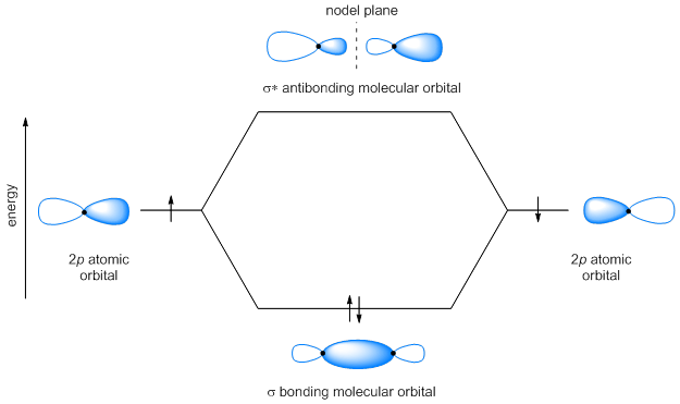
Figure 5
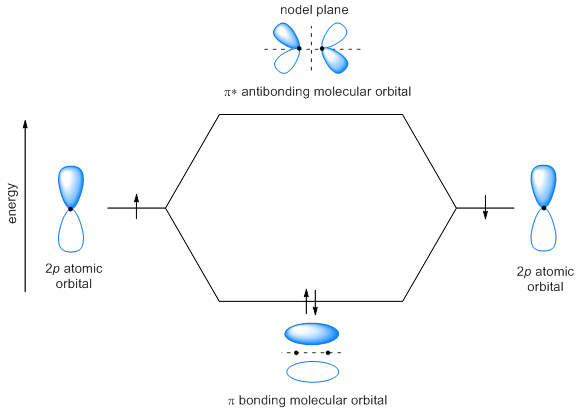
Figure 6