For most of the layers in lithography, alignment to another layer is necessary. For example, in order to make a metal line correctly, it has to be aligned to the previous layer (via layer) which connect the bottom layer to the top layer. The metal line which is printed on the top should align exactly with the bottom layer. Otherwise the connection will not function.
In ideal situation, everything will align perfectly. However, in practice the alignment will not be perfect and there will be some misalignment. If the line widths and spaces are of the size of say 65 nm, then the alignment tolerance is probably in the range of 10 nm. i.e. We would like it to align perfectly with the previous layer, but a 10 nm misalignment is tolerable. Thus even if the lines are off by 10 nm, they will conduct and the chip will function. Beyond 10 nm, this will lead to problems and ultimately to the failure of the chip.

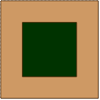
Box in Box alignment mark

Cross alignment mark
Figure 2.17 a and b. Example alignment marks
The alignment is made using standard marks called alignment marks. A few examples are given in fig 2.17 a and b. Figure 2.17 a is called “box in box” (i.e. one box would be at the bottom layer and there will be a box on the mask of the top layer). These marks are sometimes called “Fiducials”. The machine will align the box in the mask such that it will exactly fall at the center of the other box. Another example, shown in fig 2.17 b, is called cross. In this case, a cross will be there on the mask and it must be aligned to fall exactly within the four square marks present in the previous layer. These marks are usually present at the corners and edges of the masks.(Please see the next paragraph for relevant details)
|