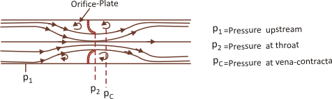
In such a device, the flow from the upstream–section accelerates as the flow-area decreases from the section 1 to 2 at the orifice. The flow continues to accelerate, or the main flow area continues to decrease till the section 2 and further downstream of the orifice at C, before it starts increasing downstream. The section at C contains the minimum flow area, known as vena–contracta.
Similar to the analysis carried out for venturimeter, one can calculate the ideal or theoretical flow rate:
|
 is defined, so that
 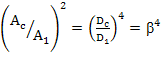 and
and 
 is the velocity-of-approach factor.
 is used to express