7.5. Column sizing approximation
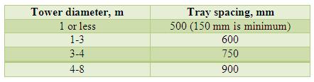
The column sizing is a trial and error calculation procedure, starting with a tentative tray layout. The calculation is then revised until anacceptable design is obtained subject to satisfying the tray pressure drop, weeping, flooding and liquid entrainment limits. The column sizing is carried at the tray where the anticipated column loading is the highest and lowest for each section. However, the vapor flow rates have the highest impact on tower diameter. For an example, the sizing calculation is performed on the top tray for the above feed section and on the bottom tray for below feed section, for a single feed distillation column with one top and one bottom product. The tray spacing determines the column height. Lower tray spacing is desirable to minimize construction cost by checking against the column performance criteria. The suggested tray spacing (Tt) with column diameter is appended below ( [1] page 162 ). The detailed column sizing calculations are discussed in the solved example.
7.6. Provisional plate design
7.6.1. Column diameter
The column diameter is determined from the flooding correlation for a chosen plate spacing. The superficial vapor/gas velocity (Unf) at flooding through the net area relates to liquid and vapor densities according to Fair's correlation ( refer to section 7.3.1 ). Csbf is an empirical constant, depends on tray spacing and can be estimated against the flow parameter (FLG) based on mass flow rate of liquid (L ) and vapor (V ) ( [3] page 567, [4] page 14-27 ).
Typically, the design velocity (Un) through the net area is about 80 to 85% of Unf for non-foaming liquids and 75% or less for foaming liquid depending on allowable plate pressure drop and entrainment. It is a common practice to have uniform tower diameter in all sections of the column even though the vapor/gas and liquid loadings are expected to be different to minimize the cost of construction. The uniformity in tower diametermay require selecting different plate spacing in different sections of the tower.
7.6.2. Hole diameter, hole pitch and plate thickness
The plate hole diameters (dh) from 3 to 12 mm are commonly used. The bigger sizes are susceptible to weeping. The holes may be drilled or punched and the plate is fabricated from stainless steel and other alloys than carbon steel. The centre to centre distance between two adjacent holes is called hole pitch (Ip) . Perforations can be arranged in square or equilateral triangular arrays with respect to the vapor/gas flow direction. The normal range of Ip is from 2.5 to 5 times of dh ( [1] page 168 ).
| For triangular pitch : |
(7.15) |
Plate thickness (tt) typically varies from 0.2 to 1.2 times of the hole diameter and should be verified by checking the allowable plate pressure drop ( [3] page 576 ).