Q – slurry feed rate, m3 /hr; di – internal diameter of the inlet, cm; d0 – internal diameter of overflow, cm; du – internal diameter of underflow, cm; D- diameter of cyclone, cm; v- volume fraction of solids in feed; h- distance between bottom of vortex finder to the top of underflow orifice, cm; ρs : ρf – density of solids and fluid respectively, kg/m3
Inlet orifice area should be 6-8% of the cross sectional area of feed chamber, vortex finder diameter is 35-40% of cyclone diameter, cylindrical section length is equal to the diameter of feed chamber, angle of conical section is equal to 12° for cyclone diameter less than 300 mm and 20° for cyclone diameter greater than 300 mm, underflow orifice diameter is equal to 25% of vortex finder diameter.
If the hydro cyclone of above geometry has to be designed, then d50 can be estimated as:
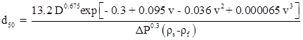 ..............(5.31)
ΔP – pressure drop across the cyclone (kPa)
The relationship between Q and ΔP is: Q = 9.4 × 10⁻³ ΔP 0.5 D2 . The D50 base point can be estimated as: D 50b = 2.86 D 0.66 , where D – cyclone diameter, cm; D50b – base diameter, μm.
The above equation is simple and indicates that D50b increases as the cyclone diameter increases. The equation is applicable to standard hydrocyclone geometry. The standard configuration can be stated as: cyclone of diameter, D; inlet slurry diameter, 0.5D; vortex finder diameter d0 , 0.35 D; cylindrical section length, 0.35D; cone angle of 10-20° ; apex orifice, (0.1-0.35) D. All these standard operating conditions are for water as a fluid, particles (quartz) of specific gravity 2.65 feed solid concentration < 1% v/v and pressure drop ΔP = 69 kPa. In case if the above condition cannot be satisfied then the correction factors have to be used.