Table 5.1:
d p , μm |
w i |
d p /d pc |
Ei , % |
wi Ei % |
1 |
0.03 |
0.11 |
0 |
0.0 |
5 |
0.20 |
0.55 |
23 |
4.6 |
10 |
0.15 |
1.11 |
55 |
8.25 |
20 |
0.20 |
2.22 |
83 |
16.6 |
30 |
0.16 |
3.33 |
91 |
14.56 |
40 |
0.10 |
4.44 |
95 |
9.5 |
50 |
0.06 |
5.55 |
96 |
5.7 |
60 |
0.03 |
6.66 |
98 |
2.94 |
>60 |
0.07 |
- |
100 |
7.0 |
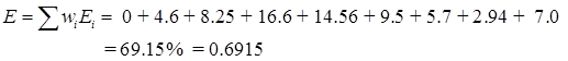
The overall collection efficiency is therefore
3. GAS LIQUID SEPARATOR
A gas-liquid separator is a vessel into which a liquid and gas mixture is fed and wherein the liquid is separated by gravity, falls to the bottom of the vessel, and is withdrawn. The gas travels upward at a design velocity which minimizes the entrainment of any liquid droplets in the gas as it exits the top of the vessel. The gas liquid feed mixture can be under pressure at the inlet of the separator. In ideal case gas liquid separator should give the maximum liquid recovery and should have low pressure of feed stream to atmospheric pressure at the discharge from the separator. This may not be accomplished in a single stage and may need number of stages. Usually from economic point of view, number of stages can be 3 to 4. As far as possible the gas and liquid should flow without any application of motive power.
While designing it is assumed that gas and liquid phase are in thermodynamic equilibrium with each other
Let the feed of gas liquid mixtures: f kg moles
Let f1 , f2 , f3 are kg moles of the components in feed mixtures
F = f1 + f2 + f3
Let the moles of gas separated be: g kg moles/hr
g1 , g2 , g3 are kgmoles of components in gas
G = g1 + g2 + g3
Let the moles of liquid separated be: l kg moles/hr
l1 , l2 , l3 are kgmoles of components in liquid
L = l1 + l2 + l3
l1 = f1 – g1 ; l2 = f2 – g2 and so on……..
g1 = G.k1 (l1 /L) ; g2 = G.k2 (l2 /L) and so on……
k1 , k2 , k3 are defined as