Laminar flow meter
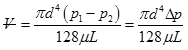
It is constructed through the collection of small tubes ![]() of sufficiently small sizes (Fig. 7.4.4) so that laminar flow is ensured and the entrance/exit losses occur within the tube assembly. Thus, the flow rate for a given fluid
of sufficiently small sizes (Fig. 7.4.4) so that laminar flow is ensured and the entrance/exit losses occur within the tube assembly. Thus, the flow rate for a given fluid ![]() becomes direct function of pressure difference
becomes direct function of pressure difference ![]() .
.
 |
(7.4.5) |
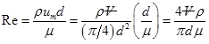
Since the flow is laminar, the Reynolds number ![]() is within 2000. One may rewrite the expression of Reynolds number as follows;
is within 2000. One may rewrite the expression of Reynolds number as follows;
 |
(7.4.6) |
Combining the Eqs (7.4.5 & 7.4.6), the design selection of ![]() , for a laminar flow meter can be set for certain range of pressure drop and flow Reynolds number.
, for a laminar flow meter can be set for certain range of pressure drop and flow Reynolds number.
(7.4.7) |
In contrast to obstruction flow devices, the volume flow has a linear relation with pressure drop for a laminar flow meter. It allows the operation of this device for wide range of flow rates for a given pressure differential, within an uncertainties of ± 4%. However, being small in sizes, the laminar tube elements are subjected to clogging when used with dirty fluids.
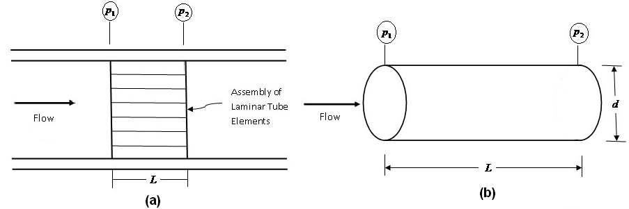
Fig. 7.4.4: (a) Basic principle of a laminar flow meter; (b) A laminar flow element.
Thermal mass flow meter
A direct measurement of mass flow of gases can be accomplished through thermal energy transfer (Fig. 7.4.5). The flow takes place through a precision tube fitted with an electric heater. Both upstream and downstream sections have externally wounded resistance temperature detectors (RTDs) typically made out of platinum with probe diameter of about 6mm. The first sensor measures the temperature of the gas flow at the point of immersion while the second senor is heated to a temperature of 20ºC above the first sensor. As a result, the heat transfer to the gas from the second sensor takes place through convection which is proportional to the mass velocity ![]() of the gas. The two sensors are connected to a Wheatstone bridge circuit for which the output voltage is proportional to the mass velocity. This circuit can be specially designed so that linearly varying output can be obtained from the circuit. The experiment is normally performed with nitrogen and a calibration factor is obtained for subsequent use of other gases.
of the gas. The two sensors are connected to a Wheatstone bridge circuit for which the output voltage is proportional to the mass velocity. This circuit can be specially designed so that linearly varying output can be obtained from the circuit. The experiment is normally performed with nitrogen and a calibration factor is obtained for subsequent use of other gases.
It is to be noted that the mass velocity of the gas is measured at the point of immersion. For the flow system with varying velocities, several measurements are necessary to obtain an integrated mass flow across the channel. Velocities of the gases in the range of 0.025m/s to 30m/s can be measured with this device within an uncertainty level of ± 2%.
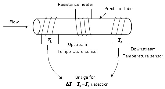
Fig. 7.4.5: Basic principle of a thermal mass flow meter.