Overview
Accurate measurement in a flowing medium is always desired in many applications. The basic approach of the given measurement technique depends on the flowing medium (liquid/gas), nature of the flow (laminar/turbulent) and steady/unsteadiness of the medium. Accordingly, the fluid flow diagnostics are classified as measurement of local properties (velocity, pressure, temperature, density, viscosity, turbulent intensity etc.), integrated properties (mass and volume flow rate) and global properties (flow visualization). Also, these properties can be measured directly using certain devices or can be inferred from few basic measurements. For instance, if one wishes to measure the flow rate, then a direct measurement of volume/mass flow can be done during a fixed time interval. However, the secondary approach is to measure some other quantity such as pressure difference and/or fluid velocity at a point in the flow and then calculate the flow rate using suitable expressions. In addition, flow-visualization techniques are sometimes employed to obtain an image of the overall flow field. The parameters of interest for incompressible flow are the fluid viscosity, pressure/temperature, fluid velocity and its flow rate.
Measurement of Viscosity
The device used for measurement of viscosity is known as viscometer and it uses the basic laws of laminar flow. The principles of measurement of some commonly used viscometers are discussed here;
Rotating Cylinder Viscometer: It consists of two co-axial cylinders suspended co-axially as shown in the Fig. 7.1.1. The narrow annular space between the cylinders is filled with a liquid for which the viscosity needs to be measured. The outer cylinder has the provision to rotate while the inner cylinder is a fixed one and has the provision to measure the torque and angular rotation. When the outer cylinder rotates, the torque is transmitted to the inner stationary member through the thin liquid film formed between the cylinders. Let ![]() be the radii of inner and outer cylinders, h be the depth of immersion in the inner cylinder in the liquid and
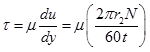
be the radii of inner and outer cylinders, h be the depth of immersion in the inner cylinder in the liquid and ![]() is the annular gap between the cylinders. Considering N as the speed of rotation of the cylinder in rpm, one can write the expression of shear stress
is the annular gap between the cylinders. Considering N as the speed of rotation of the cylinder in rpm, one can write the expression of shear stress ![]() from the definition of viscosity
from the definition of viscosity ![]() , as given below;
, as given below;
 |
(7.1.1) |
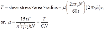
This shear stress induces viscous drag in the liquid that can be calculated by measuring the toque through the mechanism provided in the inner cylinder.
 |
(7.1.2) |
Here, C is a constant quantity for a given viscometer.
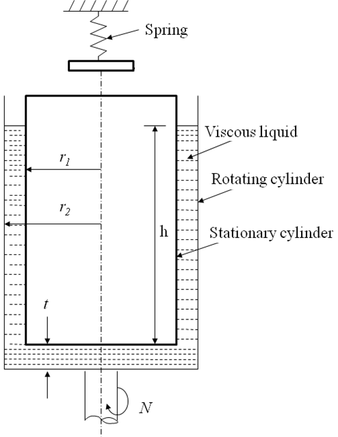
Fig. 7.1.1: Schematic nomenclature of a rotating cylinder viscometer.