2.4 Manufacturing of Carbon Fibres from PAN Precursors, Viscose and Pitch Fibres
(6 Lectures)
|
| Introduction to Carbon Fibres and PAN based Carbon Fibres |
The development of carbon fibres has been a distinct achievement in the progress of high performance fibres. The term carbon fibre refers to materials (filaments, yarns, roving) consisting of at least 92% (mass fraction) carbon, usually in the non-graphitic state. The attractive attributes of carbon fibres are: |
 |
low density, |
|
high specific strength and stiffness, |
|
excellent chemical stability (except in highly oxidizing environments), |
|
biocompatibility |
|
low coefficient of thermal expansion, |
|
excellent fatigue and creep behaviour. |
|
Owing to the amazing structural properties, carbon fibres are used extensively in fibre-reinforced composites for the replacement of metals in the most critical applications such as:
|
|
aerospace |
|
defence |
|
nuclear technology |
|
automobile |
|
marine applications |
|
sports goods |
|
civil construction |
|
biomedical etc. |
|
The use of carbon filaments in electric lamp was first patented by Thomas Alva Edison in 1877. These carbon filaments had poor mechanical properties and during 1950’s there was an added impetus to make stronger carbon fibres.
|
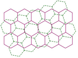
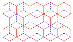
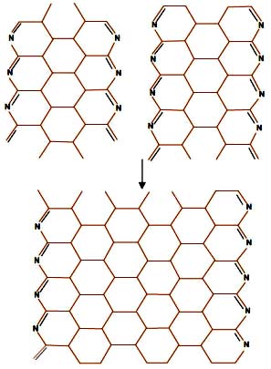
As shown in Figure 1, the carbon fibres are composed of large aromatic sheets similar to those in graphite. In carbon fibre, these aromatic sheets are randomly oriented to each other and such a arrangement is also described as ‘turbostratic’ structure while, in graphite the adjacent aromatic sheets overlap with one carbon atom at the centre of each hexagon (Figure 1(b)).
|
|
|
(a) Irregular stacking |
(b) regular stacking |
Figure 1. Stacking of aromatic sheets in (a) carbon fibres and (b) in graphite |
|
Carbon fibres are produced by controlled oxidation and carbonization of organic precursor fibres. The organic precursor fibre used for manufacture of carbon fibre, is generally a special textile polymeric fibre that can be carbonized without melting. The ideal requirements for a precursor are:
|
- Should easily convert to carbon fibre
- Should give a high carbon yield and
- The process should be economically
|
Among the various precursors, evaluated for manufacturing carbon fibres, only the following three precursors- are commercially successful. |
- Viscose rayon
- Mesophase pitch, and
- Polyacrylonitrile (PAN) fibres
|
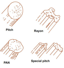
| The cross-sectional shape of these precursors are shown in Figure 2. |
|
Figure 2. Cross-sectional shapes of different precursor fibres
|
Out of these, viscose rayon (carbon yield ~ 30%) is losing its importance in competition to high performance carbon fibres available from other precursors. Pitch based carbon fibres, however, with high resultant modulus. General purpose carbon fibres obtained from isotropic pitch have higher yield of ~80% and possess modest level of strength and modulus.They are most economical and are useful in enhancing modulus and conductivity in various applications. Mesophase pitch fibres can be heat-treated to enhance to produce very high modulus carbon fibres.
|
PAN based carbon fibres are the strongest available carbon fibres. The PAN based precursors are preferred due to following reasons:
|
- high carbon yield (50-55%)
- potential of polymer to undergo cyclization reactions,
- lowest fraction of voids (resulting in higher strength and stability) coupled with the flexibility for tailoring structure of final product
|
The production process of carbon fibres involves two distinct steps: |
- Preparation of suitable organic precursor fibre
- Conversion of precursor fibre to carbon fibre
|
The physical properties of carbon fibres vary over a very broad domain owing to the differences in the nature of the precursor and processing conditions employed for conversion to carbon fibres. The properties of carbon fibres depend both on the properties of initial polymer and processing conditions used in the carbon fibre production process. Another important characteristic of carbon fibres is that they can survive very high number of stress cycles compared to steel as they are not subject to creep and fatigue failure. In carbon fibres, the conduction of heat occurs by lattice vibrations while the electricity is conducted by diffusion of electrons and holes. |
|
The potential for PAN as a precursor was first recognized in Japan in the late 1950s followed by UK and USA in 1960s. Starting with a linear PAN homopolymer containing 68% carbon, a controlled transformation is affected through a series of heat treatment steps in different environments at progressively increasing temperatures. |
PAN based carbon fibres are classified according to the tensile properties and the heat treatment temperature as follows.
|
Classification based on Properties |
- Ultra-high-modulus, type UHM (modulus >450 GPa)
- High-modulus, type HM (modulus between 350-450 GPa)
- Intermediate-modulus, type IM (modulus between 200-350 GPa)
- Low modulus and high-tensile, type HT (modulus < 100 GPa, tensile strength > 3.0 GPa)
- Super high-tensile, type SHT (tensile strength > 4.5 GPa)
|
| Classification based on Final Heat Treatment Temperature: |
-
Type-I, high-heat-treatment carbon fibres (HTT), where final heat treatment temperature is above 2000 ºC and can be associated with high-modulus type fibre.
- Type-II, intermediate-heat-treatment carbon fibres (IHT), where final heat treatment temperature is around or above 1500 ºC and can be associated with high-strength type fibre.
- Type-III, low-heat-treatment carbon fibres, where final heat treatment temperatures not greater than 1000 ºC. These are low modulus and low strength materials
|
Table1. Classification and Typical Properties of PAN based Carbon Fibres
|
Carbonization temperature & properties |
High strength |
High modulus |
Ultra high modulus |
Carbonization temperature (°C) |
1200-1400 |
1800-2500 |
2800-3000 |
Carbon % in the fibre |
92-96 |
99 |
99 |
Filament diameter (μm) |
5.5- 8.0 |
5.4-7.0 |
8.4 |
Density (g/cm3) |
1.75-1.80 |
1.78-1.81 |
1.96 |
Tensile strength (MPa) |
3105-4555 |
2415-2555 |
1865 |
Tensile modulus (GPa) |
228-262 |
359-393 |
(483-690), 577 |
Elongation at break (%) |
1.3-1.8 |
0.6-0.7 |
0.38 |
|
For graphite crystals a theoretical value of 1000 GPa has been calculated while the actual reported value is 400 GPa. The variation of Young’s modulus with direction in a graphite crystals at 8° inclination is one–tenth of the 0° modulus value. |
|
Characteristics of Acrylic Precursors suitable for Carbon Fibre
|
The structure and properties of carbon fibre are dependent on the initial precursor fibre properties as well as the conversion process governing the structural changes taking place during the formation of carbon fibre. Hence, in order to obtain carbon fibres with superior mechanical properties, acrylic precursor fibre should possess high tenacity and modulus and during the transformations induced by heating of polyacrylonitrile (under optimum conditions), the initial supermolecular structure of PAN and orientation of chains within each fibril are required to be improved (or at-least maintained). This means that the spinning process should result in defect free highly oriented fibres. Additionally the polymer characteristics such as molecular weight, comonomer type and composition of precursor polymer also have a strong influence on the spinnability of precursor polymer, properties of precursor fibre and processability of precursor fibre to carbon fibres. The following flow chart (Figure 3) explains the influence of the precursor polymer and fibre characteristics on the properties of final carbon fibre properties.
|
Related Properties of polymers |
Related Properties of fibres |
|
|
Figure 3. Effect of polymer properties on carbon fibre properties
|
|
PAN precursors used for production of carbon fibres are known as special acrylic fibres (SAF). SAF forming polymer should possess following properties:
|
- High molecular weight (Mw~200000-500000)
- An appropriate polydispersity (MWD= 2-3)
- Minimum molecular defects
- Nature and proportion of comonomers
|
The precursor fibre should have following properties-
|
- A fine denier (1-2 dtex)/ defect free fibre
- Absence of foreign particles/impurities
- Less number of filaments per tow
- High strength and modulus ( high axial orientation of molecular chains)
- A broad exothermic peak due to nitrile group cyclization during stabilization initiating at a lower temperature.
- Should result in high carbon yield (>50 %)
|
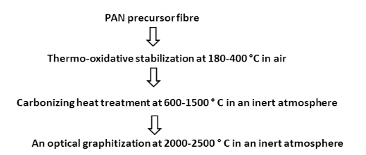
Principles of Production of carbon fibres from PAN precursors |
The manufacturing of carbon fibres based on acrylic fibres involves three successive stages of heat treatment: |
|
Figure 4. Steps for conversion of PAN precursor to carbon fibre
|
|
Why is the stabilization necessary prior to carbonization?
|
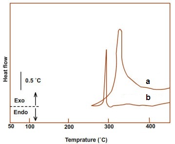
The thermal stabilization of PAN precursor is the most crucial step in the production of carbon fibres. It converts the PAN precursor into thermally stable structure capable of withstanding high temperature processing in subsequent steps. The stabilization of precursor can be accomplished either by heat-treatment in inert or oxidizing atmosphere. The stabilization in inert atmosphere (curve b in Figure 5) is faster and produces carbon fibres with poor mechanical properties with low carbon yield( 30-40% at 1000 °C).However, stabilization in air/oxygen atmosphere (curve a in Figure 5) takes longer to complete cyclization reaction and produces carbon fibres with good mechanical properties and higher carbon yield(~ 60% at 1000 °C). Also, fusion of oxygen containing groups in the polymer backbone provides greater stability to the ladder polymer to sustain high temperature carbonization treatment. The precursor is stabilized by controlled heating (180-300 °C) in oxidative environment to form a thermally stable structure capable of withstanding high temperature processing in subsequent steps at high rates with good yield. |
|
Figure 5. DSC exotherms of PAN in (a) air and (b) nitrogen.
|
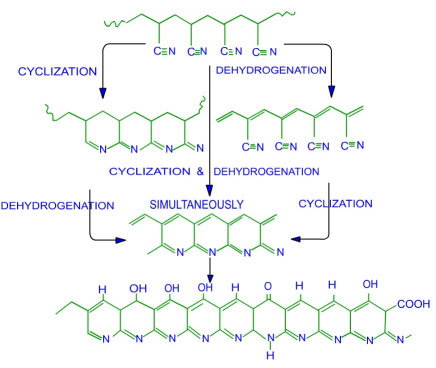
The stabilization chemistry is complex and in the presence of oxygen is accompanied by chain scission, cross-linking, dehydrogenation, formation of oxygen containing groups and cyclization take place. The chemical reactions are responsible for change in the colour of the precursor fibre to yellow, brown and ultimately black. |
|
Figure 6. Sequence of reactions occurring during stabilization |
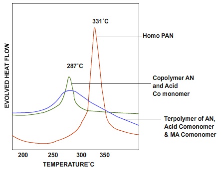
The cyclized structure is stable towards heat and can be converted to turbostatic carbon on subsequent carbonization at high temperatures. Since this cyclization reaction is highly exothermic, attempts have been made to choose PAN precursor and stabilization conditions in such a manner that the heat released during the stabilization process is dissipated without adversely affecting the properties of ultimate carbon fibre. Therefore, comonomers containing 0.5 to about 2 mole% acidic comonomers, such as itaconic acid are used (higher amounts would reduce the carbon yield).These monomer lowers the stabilization temperature. Incorporation of neutral acrylate monomers slows down the cyclization reaction and reduces the heat release rate. Both these effects facilitate stabilization reaction. A qualitative curve showing the effect of presence of comonomers is shown in Figure 7. |
The acidic comonomers such as acrylic acid (AA), methacrylic acid (MAA) and itaconic acid (IA) increase the segmental mobility, modify the fibre morphology, improve the polymer solubility as well as spinnability, lower the glass transition temperature, increases the hydrophilicity and facilitate and depress the onset point of cyclization of nitrile groups during thermo-oxidative stabilization of acrylic precursors prior to carbonization. The comonomer leads to controlled stabilization process paving path for manufacturing of PAN based carbon fibres with superior properties. The effectiveness of different monomers in reducing the initiation temperature of cyclization can be expressed in the order itaconic acid>methacrylic acid>acrylic acid>acrylamide. The superiority of itaconic acid can be attributed to the presence of two carboxylic acid groups, increasing the possibility of interaction with nitrile group.
|
Incorporation of neutral acrylate monomers slow down the cyclization reaction and to reduce the heat release rate. Neutral acrylate monomers also act as stabilizers and aid the spinning process. Both these effects facilitate stabilization reaction. Figure 7 shows a qualitative showing the effect of presence of comonomers. |
|
Figure 7. Effect of comonomers on structure stabilization |
The process of stabilization involves three main phenomena: |
|
mass transfer |
|
heat transfer |
|
shrinkage |
|
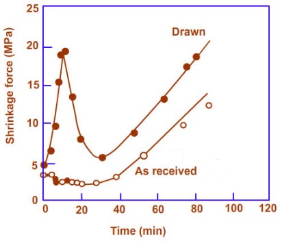
Mass transfer occurs due to diffusion of oxygen into the precursor fibres and evolution of volatile products such as HCN, NH3, and water vapour. Heat transfer takes place due to occurrence of exothermic reaction of stabilization. The stabilization process therefore is diffusion controlled and rate of diffusion is in fact the rate determining step of cyclization reaction. For the same reason finer fibres with high surface area are preferred. Therefore, the special acrylic fibre suitable for precursor application is drawn at least 12-16 times. The fibre also undergoes substantial physical as well as chemical shrinkage. As shown in Figure 8, the physical shrinkage is attributed to the entropic recovery of a drawn and quenched fibre. The chemical shrinkage occurs mainly due to the formation of cyclized ladder structure. |
|
|
Figure 8. Shrinkage of fibre with stabilization time |
Effect of process conditions during thermo-oxidative stabilization
|
The stabilization process is greatly influenced by the tension during thermo-oxidative stabilization, the heat treatment temperature, the treatment medium, pre-stabilization treatments, and the characteristics of the precursor. |
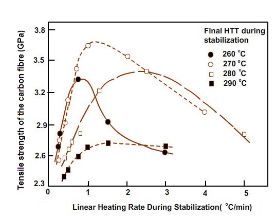
As this is an exothermic reaction, the manner in which heat dissipation takes place decides the further performance of the fibre. In order to achieve this, slow heating rate must be used to avoid run-away reactions occurring during the stabilization process. As shown in Figure 9, excessive heating (higher stabilization temperature) results in poor properties due to burning out of fibre while insufficient heating (lower stabilization temperature) leads to incomplete reaction and damage of fibre during carbonization step. Stabilization can be achieved isothermally by heating at constant temperature, but is time consuming. Alternate more practical methods are step wise increase in temperature or one-step stabilization, with temperature rising along a tubular furnace. |
|
|
|
Figure 9. Effect of heating rate and final stabilization temperature on properties of carbon fibres |
The chemical structural changes occurring during stabilization are discussed in detail in several reviews and books. This step is the decisive step as it largely governs the final structure of fibre and hence it’s ultimate mechanical properties. |
|
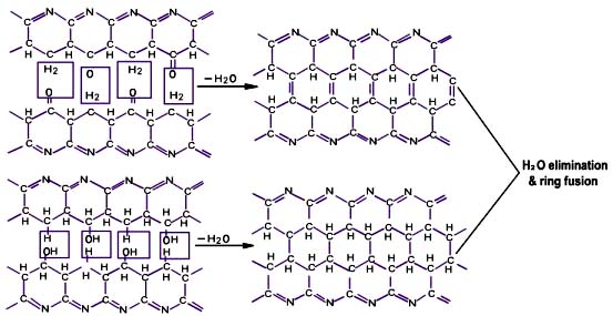
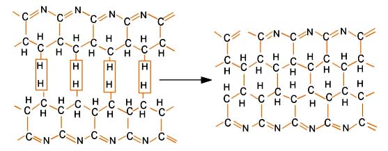
This step involves heat treatment of stabilized PAN fibre in an inert atmosphere under low or very little tension. Chemically, carbonization is the process of fusion of ladder polymer chains of stabilized fibres and elimination of all elements other than carbon to form graphite like structure. As shown in Figure 10, the carbonization process is carried out in two different heating zones. The first heating zone, in which fibres are treated up to 600 °C, is very crucial and involves intermolecular crosslinking of stabilized fibre elimination of water or other gases. This zone, requires a low heating rate (less than 5 °C/min) so as to keep the mass transfer slow. A faster mass transfer at higher heating rates may cause surface irregularities in the form of pores. Most of the volatiles are evolved below 1000 °C, and only carbon and some nitrogen(~6%) are left. The dehydrogenation, dehydration reactions occurring in these steps are shown in Figure 11-12. |
|
|
Figure 10. Schematic representation of carbonization process |
|
Figure 11. Schematic representation of water elimination reactions |
|
Figure 12. Schematic representation of dehydrogenation reactions |
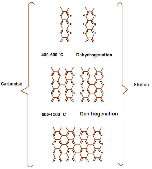
In the second zone, in which the fibres are heated between 600-1300 °C, higher heating rates can be used because of the reduced possibility of damage due to exothermic reactions. Inert gases and non-oxidizing media, such as HCl, BBr3, ZnO etc., have been used to avoid oxidative degradation at such high temperatures. Nitrogen and hydrogen cyanide are evolved due to intermolecular crosslinking of polymer chain as shown in Figure 13, and hydrogen is evolved as a result of dehydrogenation. The carbon atoms of one cyclized sequence fit into the spaces left by the nitrogen of the adjacent sequence leading to the growth of graphite like structure in the lateral direction.
|
|
|
Figure 13. Intermolecular Cross-linking of Polymer Chains |
|
This step involves heating the carbonized fibre under tension at about 1200- 3000 °C in an inert atmosphere. Nitrogen cannot be used as inert medium because above 2000 °C it becomes active and forms cyanogens by reacting with carbon fibres. This leads to an increase in the size and alignment of graphite crystals resulting in enhanced mechanical properties. |
Structure of PAN based Carbon Fibres
|
The microstructure of the polyacrylonitrile (PAN) precursors can strongly affect the structure of the carbon fibres which determine the final mechanical properties of carbon fibres. However, the physical and chemical structural transformations that take place during heat treatments are extremely complicated. The linear chain structure of PAN based precursor is transformed to a planer structure. |
Carbon fibres have a sheath core type macroscopic structure, with greater perfection and of packing and orientation of graphite layers and larger crystallites than that in the core. The difference in the fibre density (~1.8 g/cm3) and the crystal density (~2.1 g/cm3) of carbon fibres suggests the presence of an appreciable porosity (~16-18%) due to presence of sharp-edged, needle-like pores/voids in the fibre direction. |
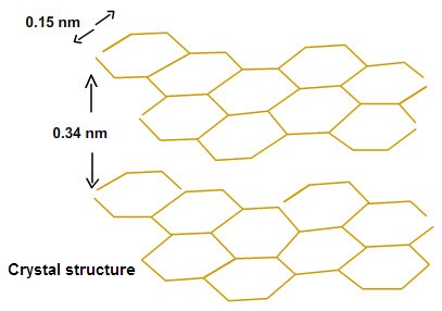
Carbon fibres consist of polyaromatic carbons and exist as turbostatic carbon,shown in Figure 14. The crystal structure of turbostatic carbon with a distance of 0.34 nm between the layers of planes is greater than that in the graphite. Wide angle X-ray diffraction has been used to obtain the characteristic parameters for carbon fibres. |
|
|
Figure 14. Crystal Structure of Turbostatic Carbon |
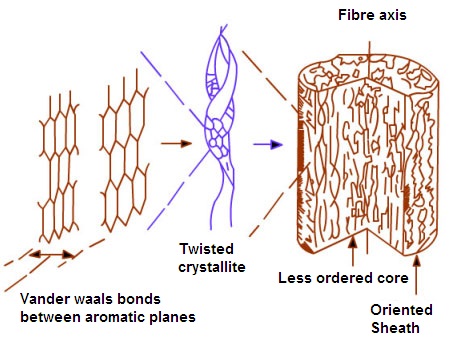
These graphitic layers form the basic structural units in the shape of ribbons of 6 nm average width and a length of several hundred nanometers. About 10 to 14 such ribbons pack in bundles to form fibrils observed in electron micrographs of carbon fibre. In the electron microscope the fibrils in carbon fibre are observed parallel to the fibre axis and the ribbons pass from one fibril to the neighbouring fibril, producing elongated gaps between the fibrils (Figure 15). During heat treatment at high temperature during graphitization, such defects in the turbostatic graphite layer migrate to form a longer stretch of perfect order and needle- like voids between graphitic crystals. |
|
Figure 15. Schematic showing structure of Carbon Fibre |
The structure of carbon fibre ribbon is believed to be a columnar arrangement of disoriented graphite crystallites parallel to the ribbon length. The idealized tetragonal crystallites are stacked above one another, with slight disorientation between the crystals in the direction of fibre axis, trapping sharp needle-like voids, where the boundaries between the stacks represent the disordered regions. |
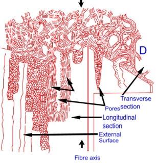
In a more recent description of carbon fibre structure representing differences in sheath and core is shown in Figure 16. The sheath region appears to be more ordered and lamellar while in the core, extensive folding can occur. The model also demonstrates the interlinked crystallinity of HM carbon fibre showing tilt, twist boundaries, porosity and overlapping boundaries. |
|
Figure 16. Model explaining structure of high strength PAN-based carbon fibre
|
Carbon Fibres from Cellulosic Precursors
|
Cellulose is the second important raw material for large- scale production of carbon fibres because it degrades without melting. Cellulosic precursor fibres, although of considerable historic significance, are no longer an important source of carbon fibres. To make continuous carbon fibres continuous viscose fibre precursor is required, which immediately imposes a limitation, since majority of current viscose production is chopped to form a staple product. Secondly, specific end-users superimpose their own stringent specifications, like presence of certain trace elements etc. The most common end uses for these carbon fibres are ablative shields and high temperature packing materials. |
Contrary to PAN and pitch precursors, limited information is available on production of carbon fibres from cellulosic precursors. |
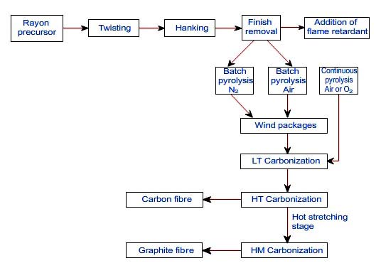
Production of Carbon Fibres from Rayon
|
Different stages of production of carbon fibre from rayon precursor are shown schematically in Figure 17.
|
|
|
Figure 17. Schematic diagram showing production of cellulose based carbon fibres |
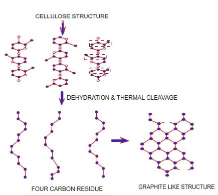
The repeat unit of cellulose in rayon contains hydrogen and oxygen, which can result in the elimination of five molecules of water resulting in a theoretical weight loss of 55.5%.The actual weight loss is about 70-90%.This excessive weight loss is attributed to chain-splitting reactions involving CO2, CO, alcohols, ketones, and a number of other carbon containing compounds.
|
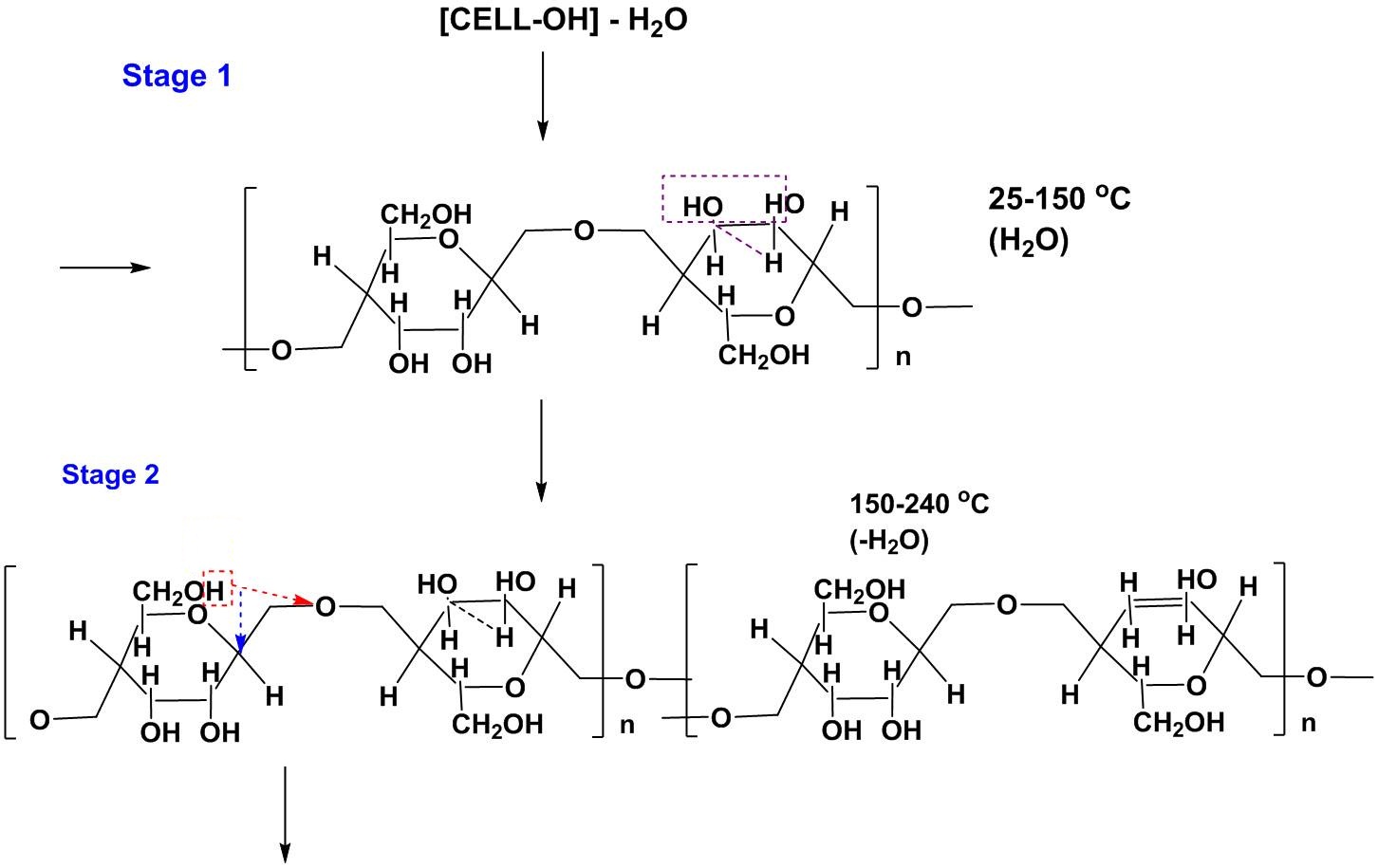
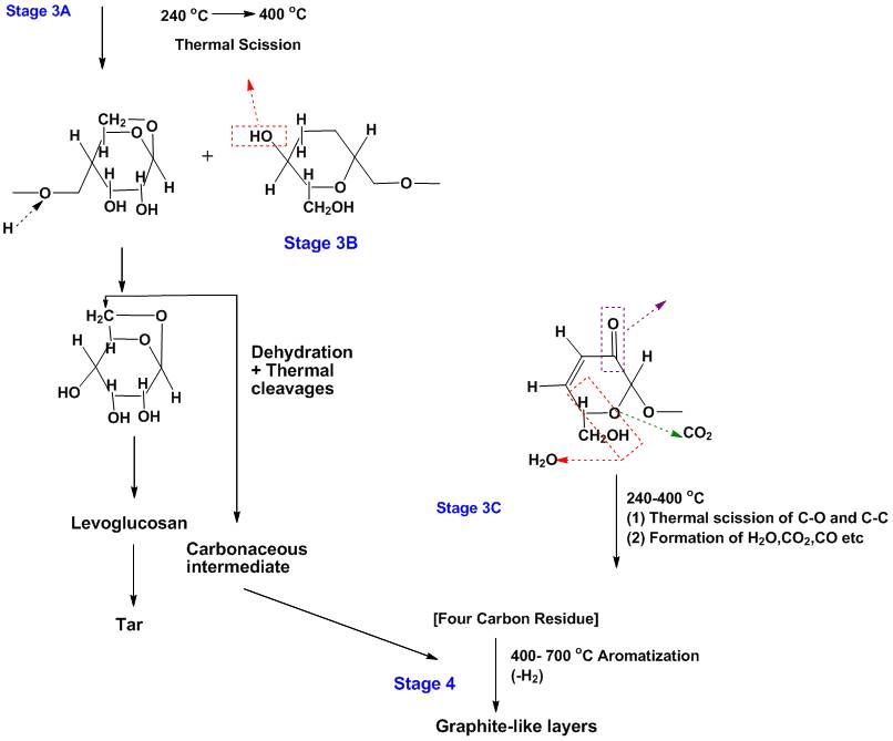
This process occurs through several stages. In the first stage, between 25-150 °C, there is physical desorption of about 12% absorbed water with a small degree of change in lateral order. This is followed by an intramolecular dehydration from the –H and –OH fragments present in the cellulosic unit between 150-240 °C. Finally, thermal cleavage of the glycosidic linkage and scission of ether bonds and some C-C bonds via free radical reaction (240-400 °C) occurs. This leads to the formation of large amount of tar, water, CO and CO2. (Figure 18)
|
|
Figure 18.
Sequence chemical reactions occurring during conversion of viscose precursor to carbon fibre |
In addition, when a glycosidic linkage is split, it forms a levoglucosan (1, 6-anhydro-β-D-glucopyranose). On pyrolysis, this levoglucosan unit breaks down to give flammable products and this reduces the ultimate yield of carbon fibre. Therefore, the formation of levoglucosan is not desirable. The dehydration reaction (stage 2) and the thermal scission (stage 3) are competitive reactions. Since the removal of CH2OH groups starts at 120 °C, the early removal of these groups can prevent the subsequent reaction leading to formation of levoglucosan at 250 °C. Hence, holding the temperature in initial stages below 250 °C is an effective way of improving the carbon yield.
|
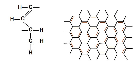
At 400 °C and above, further thermal cleavages result in the formation of carboneous intermediates and four carbon residues. Between 400 and 700°C, these structures polymerize through condensation reactions involving removal of –H above 400 °C into a carbon polymer with graphite –like structure. Interestingly, the longitudinal striations present on the surface of the original cellulose remain on the surface of carbon fibre, in spite of occurrence of variety of chemical transformations. |
|
|
Figure19. Structure of (a) four carbon residue and (b) fused structure |
Carbonization at higher temperatures ranging between 1000 and 1500 °C in inert atmosphere further improves the mechanical properties. A marked reduction in the resistivity is observed during heat treatment between 500 and 1000 °C. This has been attributed to the formation of aromatic ring structure.
|
Further graphitization of these fibres, under strain at 700-2700 °C, causes longitudinal orientation of the planes resulting in high modulus carbon fibre. The four carbon residues align themselves with long dimension parallel to the b axis, joining together to form a chain polymer along the original cellulose direction. The adjacent chains then condense to form six-carbon graphitic structures as illustrated in Figure 20. According to this scheme, the cellulose b axis, which is 10.3 Å long shrinks to twice the length of the graphitic b axis (8.25 Å). The young’s modulus of resulting graphitized fibre is directly related to the graphitization temperature and the amount of stretch applied.
|
|
Figure 20. Transformation of cellulose to graphite like structure |
Carbon Fibres from Pitch Precursors |
Preparation of Pitch Precursor
|
Pitch can be defined as thick, dark coloured bituminous substances obtained as a result of industrial destructive distillation processes, obtained as deposits on the earth surface, or manufactured from a specially selected feedstock. The properties of carbon fibres depend on the tropicity of pitch used for producing precursor fibres.
|
|
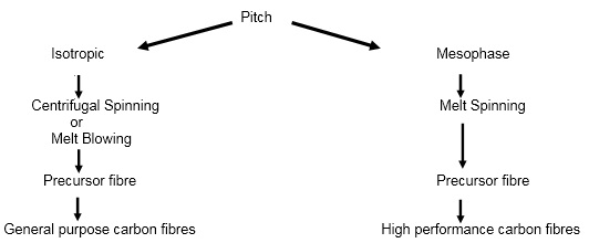
Figure 21. Steps showing conversion of pitch to carbon fibres |
The carbon fibres made from isotropic pitch have low strength and are also referred to as general purpose carbon fibres or isotropic carbon fibres. The isotropic pitches are prepared from high-boiling fractions of petroleum feedstocks, usually heavy slurry oils produced in catalytic cracking of crude oil. A typical commercial pitch is “Ashland Aerocarb 70”, which has a softening temperature of 208 °C and a viscosity of 1Pa.s at 278 °C. Pitches may be subjected to additional treatments to reduce low molecular weight components selectively. |
General purpose fibres are prepared by two different spinning methods: |
- Centrifugal Spinning
- Melt Blowing
|
In Centrifugal Spinning, molten pitch is forced through small holes in a rotating bowl. The pitch stream is attenuated into a fibre by centrifugal forces, and is directed against a cutter by a stream of air.The spun fibres may be cut into shorter lengths by a judiciously positioned knife. The fibres are then processed in the form of a tow or a mat. |
Melt Blowing process gives production rates (per spinneret hole) of the order of 10 times conventional melt spinning. In this process, a molten stream of pitch is extruded into a high velocity stream of forwarding gas, which rapidly attenuates the fibre. A commercial die is illustrated. The physics and mechanics of the process are well articulated.
|
High-performance fibres are made from Mesophase Pitch, which is a discotic liquid crystalline material, containing highly oriented molecules termed as mesophase. |
Mesophase pitch preparation has three main steps:
|
- Highly aromatic feedstock,
- Process for polymerising the molecules,
- Process for separating out the unreacted feed molecules
|
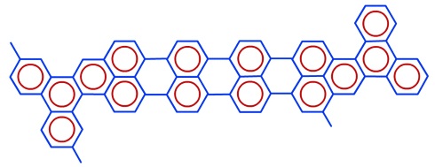
When polymerised the pitch molecule will have characteristics similar to the molecule shown in Figure 22
|
|
Figure 22. Structure of typical pitch molecule
|
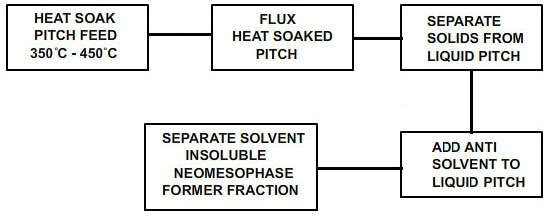
| A typical process for making mesophase pitch preparation is shown in the Figure 23 |
|
Figure 23. Process for Mesophase Pitch Preparation
|
Mesophase pitch consists of molecules of two or three aromatic molecules that are stacked face to face in slight overlapping pattern and are also known as basic structural units (BSU’s).
|
High-performance carbon fibres are typically melt spun, and spinning technology is the same for all pitch types. |
|
Figure 24. Influence of spinneret design on fibre morphology
|
The aromatic structure of molecules in mesophase pitch results in formation of optically ordered liquid crystals which are either liquid or solid depending on temperature. This affects the rheology and performance during processing. This necessitates the proper understanding of rheological behaviour of the pitch to produce uniform filaments by melt spinning. |
| Various types of fibre structures have been produced depending on the spinneret design. The typical fibre structures shown in Figure 24, are named as as ‘pacman’ radial (a), wavy radial (b) and severe ‘pacman’ (c). The fibres with ‘pacman’ cross-sections are known to have longitudinal splits which may adversely affect physical properties. In the downstream processing steps, no significant change in the structure is observed. However, the heat treatment helps in densification of the initial structure, i.e. increases the packing to increase tensile and thermal properties and modulus. |
| The use of non-round pitch carbon fibre cross-section can help in enhancement of fibre adhesion to matrices or improved surface characteristics. |
Conversion of Pitch Precursor to Carbon Fibres
|
The pitch precursor fibres, as spun are very weak and thermoplastic in nature. These need to be chemically treated to render them suitable for subsequent carbonization. This process is called stabilization or thermosetting. |
Stabilization: This is accomplished by oxidation treatment in air, O2 or an O2/N2 mixture. Several other alternative treatments using NO, SO2 or HNO3 are also known. The control of the oxidation process is critical, since underoxidized fibres will remain partly thermoplastic and may result in undesirable fusion of filaments in subsequent carbonization at higher temperatures. This will produce carbon fibre with poor tensile strength. On the other hand, over-oxidation will produce brittle product and will reduce the graphitizability of pitch.
|
An isotropic pitch has lower degree of condensation, higher hydrogen content, and a lower softening point. Therefore, isotropic pitch precursors generally require about 3 h of treatment in a 20% oxygen atmosphere to form an oxygen bridge structure. |
Adequate stabilization of a typical mesophase precursor fibre can generally be achieved in ~40-150 min by treatment at 260 °C. The time required for stabilization depends on the chosen oxidizing atmosphere, temperature, the diameter of precursor fibres, the type of pitch precursor, its mesophase content and molecular weight distribution. The average mechanical properties of mesophase fibres before and after stabilization are given in Table 2.
|
Table 2 . Properties of pitch based carbon fibres |
|
|
Carbonization process is required to remove hetero-atoms like H, N, O and S in the form of H2O, CO2, CO, N2, SO2, CH4, H2 and tars. The highest weight loss is observed to occur in the initial stages of carbonization. Therefore, an initial low temperature carbonization at 700 °C for 30 s to 5 min is carried out to avoid disruption of fibre structure. The sequence of structural changes occurring during various carbonization stages are shown in Figure 25.
|
|
Figure 25. Mesopitch and High Modulus Carbon Fibres from Pitch |
The tensile strength and modulus of carbon fibre made from mesophase pitch increase with increase in treatment temperature. This is attributed to increasing degree of perfection in the structure. With an isotropic pitch based fibre the strength and modulus change only slightly.
|
Graphitization
|
The mesophase pitch based fibres on further heat treatment under highly controlled atmosphere produces fibres with a high degree of orientation, where carbon crystallites are parallel to fibre axis. The structural changes occurring at different heat treatment stages are shown in figure below.
|
|
Figure 26. Stages of graphitization of pitch- based fibre |
|