| Primary Motions |
| Three primary motions are required in the loom for weaving. |
| • Shedding
• Picking
• Beat up |
Shedding is the operation by which the warp is divided into two parts so that sufficient gap is created between them for the uninterrupted passage of the weft from one side of the loom to the other. Picking is the operation to transfer the pick (weft) from one side of the loom to the other. In shuttle loom, picking is done from both sides. However, in shuttleless looms, it is done from only one side of the loom (generally from left). Several systems are available for the picking. Shuttle is the most traditional mode of picking and it is still being used in the industry. In shuttleless looms, following picking systems are used.
|
| • Projectile
• Air jet
• Water jet
• Rapier |
Beat up is the operation to position the newly inserted pick up to the cloth fell i.e. the boundary up to which the fabric has been woven.
|
Secondary Motions |
Two secondary motions are required in the loom for weaving. |
|
Take up motions ensure the winding of fabric continuously as soon as it is produced. Ensuring uniform pick spacing is also another function of take up motion. When the fabric is wound by the take up system, the tension in the warp increases and thus it is required to release the warp from the weaver's beam which is performed by the let off motion. |
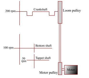
| The transmission of motions to some of the important loom components has been shown in Figure 6.1. The loom pulley (machine pulley) gets motion directly from the motor pulley. The crank shaft, which has a special design, is connected with the loom pulley. The revolution per minute (r.p.m.) of the crank shaft is equal with the loom speed (number of picks inserted per minute or picks/minute). The beat up operation is done by the reed which is carried by the sley and the latter is connected with the crank shaft. One revolution of crank shaft causes one beat up. Therefore, if 200 picks are being inserted per minute, 200 beat ups are required in one minute. Thus the r.p.m. of the crank shaft has to be 200. |
|
Figure 6.1: Transmission of motions in loom
|
| Crank shaft is connected with the bottom shaft through gears. As the name implies, bottom shaft is positioned near the floor. Picking motion is originated from the bottom shaft in case of shuttle looms. Two picking cams are mounted on the bottom shaft, one on each side. Therefore, one revolution of bottom shaft ensures the insertion of two picks. So, for inseting 200 picks per minute, bottom shaft should rotate at 100 r.p.m. The r.p.m. of bottom shaft is always half as compared to that of crank shaft. |
In case of plain weave, the healds return to the same position after every two picks. Therefore, two shedding cams can be mounted on the bottom shaft for controlling the healds. However, for other weaves where more than two healds are required, a cam shaft (also known as tappet shaft) is used. For example, in case of 3×1 twill weave, shedding cycle extends over 4 pick. In this case, 4 shedding cams are mounted on cam shaft which rotates at 50 r.p.m. The primary motions, their frequency and controlling loom shaft for plain weave and 3×1 twill weave are given in Tables 6.1 and 6.2 respectively. |
Table 6.1: Frequency of primary motions and controlling shaft for Plain weave
|
| Operation cycle |
Frequency of operation |
Loom shaft |
| Shedding |
Once/2 pick |
Bottom |
| Picking |
Once/2 pick |
Bottom |
| Beat-up |
Once/ pick |
Crank |
|
Table 6.2: Frequency of primary motions and controlling shaft for 3×1 twill weave
|
| Operation cycle |
Frequency of operation |
Loom shaft |
| Shedding |
Once/4 pick |
Cam/tappet |
| Picking |
Once/2 pick |
Bottom |
| Beat-up |
Once/ pick |
Crank |
|
| Cam Shedding Systems |
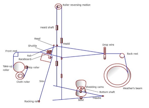
The cross-sectional view of a plain loom with cam shedding mechanism is shown in Figure 6.2. Two shedding cams are controlling two healds through the treadle levers. The tips of the treadle levers are connected with the healds with ropes and links . Each of the treadle levers carry one treadle bowl (pulley) which actually remains in contact with the shedding cams. |
|
Figure 6.2: Cross-sectional view of loom
[Courtesy : The Textile Institute, Manchester]
|
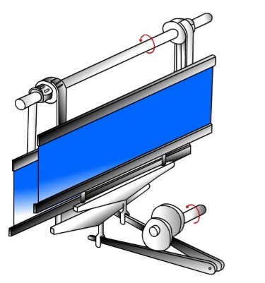
For plain woven fabrics, two shedding cams are positioned at 180° phase difference. Therefore, when one cam pushes the treadle bowl in the downward direction, the other cam accommodate the upward movement of the other treadle bowl. The upward movement of the heald is activated by the roller reversing mechanism which is positioned over the loom. Figure 6.3 presents another view of cam shedding system and roller reversing motion. |
|
Figure 6.3: Cam shedding system
[Courtesy : The Textile Institute, Manchester] |
Negative and Positive cams |
The cams used for shedding can broadly be classified under two categories. Negative cams can control only the one part (50%) of the movement of the healds (downward movement). The upward movement is ensured by the roller or spring reversing mechanism. When back heald is pushed downward, the reversing roller rotates clockwise. This causes winding of belts, connected to the front heald, on the reversing roller with smaller diameter. Thus the front heald moves upward. Similarly, when the front heald moves downward, the reversing rollers rotate anti-clockwise. So the belt, connected with the back heald, is wound on the bigger pulley of roller reversing system. As a result the back heald is lifted. Thus the entire system ensures upward and downward movements of the healds. So, the whole system can be classified as a positive system. Although the cams used for this are negative as they alone can only ensure the downward movement of the healds. |
Positive cams can control the upward and downward movement of the healds. Grooved cams (Figure 6.4) or matched cams are generally used as positive cams. |
|
Figure 6.4: A model of grooved cam |
Distinct (clear) and Indistinct (unclear) Shed |
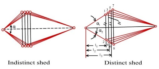
If the extent of vertical movement of the healds during shedding is same then indistinct or unclear shed is produced as depicted in left hand side of Figure 6.5. In case of indistinct shed, the position of the top shed line is different for different healds. Therefore, the shuttle actually get lower amount of space through which it has to travel. So, the possibility of abrasion and collision between shuttle and shed line is higher. |
In case of distinct or clear shed, shown in the right hand side of Figure 6.5, the position of top shed line at the front part of the shed is same irrespective of the healds. This type of shed can be formed if the extent of vertical movement of the healds during shedding is changed based on their position. The first heald, which is nearer to the cloth fell, has the minimum vertical movement and the last heald has the maximum vertical movement. The shuttle gets more space to travel in case of distinct shade as ( α1 +α2) > α. |
|
Figure 6.5: Indistinct (unclear) and distinct (clear) sheds |
Lift (throw) of the Cam |
In the preceding section, it has been discussed that higher vertical movement is required for the back heald so that distinct shed is formed. However, effective length of the treadle lever is shorter for the back heald. Thus, if the lift or throw of the cams controlling the back and front heald is same, higher vertical movement will occur for the front heald. This is just the opposite of the actual requirement. To overcome this problem, cam which is controlling the back heald possesses higher lift as compared the cam which is controlling the front heald. |
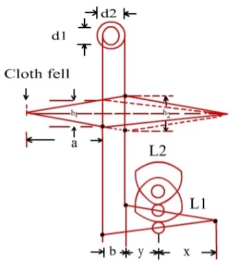
Let us consider the following parameters as shown in Figure 6.6. |
- x is the distance between the fulcrum point of treadle levers and centre of treadle bowl.
- y is the distance between the centre of treadle bowl and tip of the treadle lever tied with the back heald.
- b is the distance between the front and back heald.
- a is the distance between cloth fell and front heald.
- h1 and h2 are the lifts of the front and back healds respectively.
|
|
Figure 6.6: Lift of the cams and movement of the healds
[Courtesy : The Textile Institute, Manchester] |
The lift of a heald is equal to the movement of the tip of the corresponding treadle lever. Now, applying the concept of similar triangles, we can write |
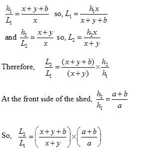 |
The above expression has two components and in both the components the numerator is clearly greater than the denominator. Therefore, the value of L2 is significantly greater than that of L1. This implies that the lift of the cam controlling the back heald is significantly greater than that of cam controlling the front heald. |
Diameter of the reversing rollers |
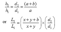
The shaft carrying the reversing rollers move clockwise and anti-clockwise to control the heald movement. The angular movement of the shaft during shedding is constant. However, it has to ensure that the back heald gets higher vertical movement than the front heald so that distinct shed is produced. This is attained by using two reversing rollers with different diameters. The roller with bigger diameter is connected with the back heald and vice versa. As the linear movement of reversing roller (angular movement × radius) is equal to the vertical movement of the corresponding heald, the following expressions can be written. |
 |
|