As seen in the figure furnace temperature  is higher than temperature of the refractory surface facing the combustion chamber of furnace which is is higher than temperature of the refractory surface facing the combustion chamber of furnace which is  . In such a situation we have to consider the heat flow from the combustion chamber furnace to the refractory surface. Similar is the case with the exterior wall of the refractory. Here temperature . In such a situation we have to consider the heat flow from the combustion chamber furnace to the refractory surface. Similar is the case with the exterior wall of the refractory. Here temperature  is greater the environment temperature is greater the environment temperature  . In both cases heat flows by convection and heat transfer coefficient should be used to determine respective surface temperatures. In the fuel fired furnaces the reaction chamber is heated by the transfer of heat of products of combustion. As such can be determined using heat transfer coefficient for forced convection heat transfer. Similarly metallic shell of the furnace is exposed to the environment and transfer of heat from shell to environment occurs by free convection and as such free convective heat transfer coefficient should be used. . In both cases heat flows by convection and heat transfer coefficient should be used to determine respective surface temperatures. In the fuel fired furnaces the reaction chamber is heated by the transfer of heat of products of combustion. As such can be determined using heat transfer coefficient for forced convection heat transfer. Similarly metallic shell of the furnace is exposed to the environment and transfer of heat from shell to environment occurs by free convection and as such free convective heat transfer coefficient should be used.
Since no heat is produced in the composite wall, the unidirectional heat flow  is constant at steady state is constant at steady state
 |
(3) |
In equation 3,  and and  are heat transfer coefficients. Note that are heat transfer coefficients. Note that  and are interface and are interface
temperatures and there is no air gap between wall 1 of thickness  and wall 2 of thickness and wall 2 of thickness  and between and and between and  . We may say contact thermal resistance is zero. Since heat flow is constant, temperature of the refractory becomes a function of . We may say contact thermal resistance is zero. Since heat flow is constant, temperature of the refractory becomes a function of  and and  . The solid continuous line shows the temperature gradient in the composite wall. . The solid continuous line shows the temperature gradient in the composite wall.
By solving equations 3 simultaneously we get.
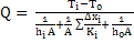 |
(4) |
Note  is thermal resistance due to convection. The equation 4 describes the heat flow through a composite wall lined with the refractory material of different thicknesses and thermal conductivities. is thermal resistance due to convection. The equation 4 describes the heat flow through a composite wall lined with the refractory material of different thicknesses and thermal conductivities.
|