Lecture 11 & 12
Resistance Welding
Resistance welding processes are pressure welding processes in which heavy current is passed for short time through the area of interface of metals to be joined. These processes differ from other welding processes in the respect that no fluxes are used, and filler metal rarely used. All resistance welding operations are automatic and, therefore, all process variables are preset and maintained constant. Heat is generated in localized area which is enough to heat the metal to sufficient temperature, so that the parts can be joined with the application of pressure. Pressure is applied through the electrodes.
The heat generated during resistance welding is given by following expression:
H = I 2 R T
Where, H is heat generated
I is current in amperes
R is resistance of area being welded
T is time for the flow of current.
The process employs currents of the order of few KA, voltages range from 2 to 12 volts and times vary from few ms to few seconds. Force is normally applied before, during and after the flow of current to avoid arcing between the surfaces and to forge the weld metal during post heating. The necessary pressure shall vary from 30 to 60 N mm-2 depending upon material to be welded and other welding conditions. For good quality welds these parameters may be properly selected which shall depend mainly on material of components, their thicknesses, type and size of electrodes.
Apart from proper setting of welding parameters, component should be properly cleaned so that surfaces to be welded are free from rust, dust, oil and grease. For this purpose components may be given pickling treatment i.e. dipping in diluted acid bath and then washing in hot water bath and then in the cold water bath. After that components may be dried through the jet of compressed air. If surfaces are rust free then pickling is not required but surface cleaning can be done through some solvent such as acetone to remove oil and grease.
The current may be obtained from a single phase step down transformer supplying alternating current. However, when high amperage is required then three phase rectifier may be used to obtain DC supply and to balance the load on three phase power lines.
The material of electrode should have higher electrical and thermal conductivities with sufficient strength to sustain high pressure at elevated temperatures. Commonly used electrode materials are pure copper and copper base alloys. Copper base alloys may consist of copper as base and alloying elements such as cadmium or silver or chromium or nickel or beryllium or cobalt or zirconium or tungsten. Pure tungsten or tungsten-silver or tungsten-copper or pure molybdenum may also be used as electrode material. To reduce wear, tear and deformation of electrodes, cooling through water circulation is required. Figure 11.1 shows the water cooling system of electrodes.
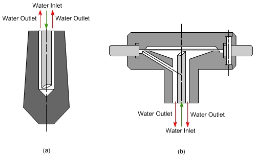
Fig 11.1: Water Cooling of Electrodes (a) Spot Welding (b) Seam Welding.
Commonly used resistance welding processes are spot, seam and projection welding which produce lap joints except in case of production of welded tubes by seam welding where edges are in butting position. In butt and flash welding, components are in butting position and butt joints are produced.
1. Spot Welding
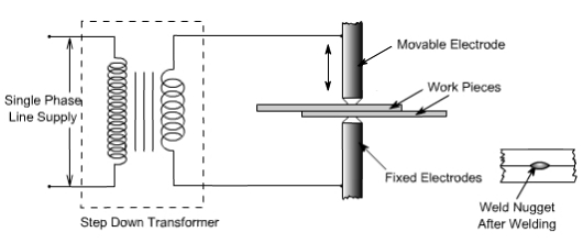
Fig 11.2: Principle of Resistance spot Welding
The welding cycle starts with the upper electrode moving and contacting the work pieces resting on lower electrode which is stationary. The work pieces are held under pressure and only then heavy current is passed between the electrodes for preset time. The area of metals in contact shall be rapidly raised to welding temperature, due to the flow of current through the contacting surfaces of work pieces. The pressure between electrodes, squeezes the hot metal together thus completing the weld. The weld nugget formed is allowed to cool under pressure and then pressure is released. This total cycle is known as resistance spot welding cycle and illustrated in Figure 11.3
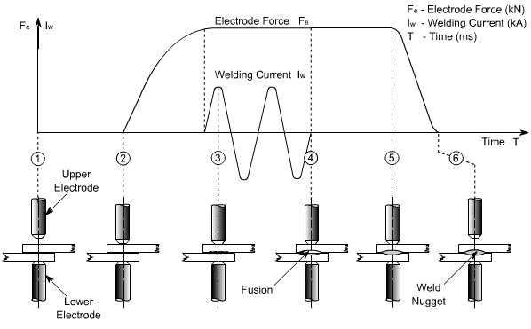
Fig 11.3: Resistance Spot Welding Cycle
Spot welding electrodes of different shapes are used. Pointed tip or truncated cones with an angle of 120° - 140° are used for ferrous metal but with continuous use they may wear at the tip. Domed electrodes are capable of withstanding heavier loads and severe heating without damage and are normally useful for welding of nonferrous metals. The radius of dome generally varies from 50-100 mm. A flat tip electrode is used where minimum indentation or invisible welds are desired.
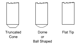
Fig 11.4: Electrode Shapes for Spot Welding
Most of the industrial metal can be welded by spot welding, however, it is applicable only for limited thickness of components. Ease of mechanism, high speed of operation and dissimilar metal combination welding, has made is widely applicable and acceptable process. It is widely being used in electronic, electrical, aircraft, automobile and home appliances industries.
2. Seam Welding:
In seam welding overlapping sheets are gripped between two wheels or roller disc electrodes and current is passed to obtain either the continuous seam i.e. overlapping weld nuggets or intermittent seam i.e. weld nuggets are equally spaced. Welding current may be continuous or in pulses. The process of welding is illustrated in Figure 11.5.
Fig 11.5: Process of Seam welding
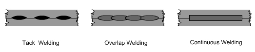
Fig 11.6: Type of Seam Welds
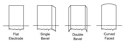
Fig 11.7: Electrode Shapes of Seam Welding
Overlapping of weld nuggets may vary from 10 to 50 %. When it is approaching around 50 % then it is termed as continuous weld. Overlap welds are used for air or water tightness.
It is the method of welding which is completely mechanized and used for making petrol tanks for automobiles, seam welded tubes, drums and other components of domestic applications.
Seam welding is relatively fast method of welding producing quality welds. However, equipment is costly and maintenance is expensive. Further, the process is limited to components of thickness less than 3 mm.
3. Projection Welding:
Projections are little projected raised points which offer resistance during passage of current and thus generating heat at those points. These projections collapse under heated conditions and pressure leading to the welding of two parts on cooling. The operation is performed on a press welding machine and components are put between water cooled copper platens under pressure. Figures 11.8 and 11.9 illustrate the principle of resistance projection welding.
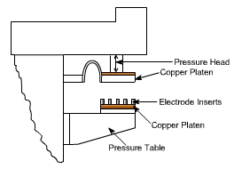
Fig 11.8: Resistance Projection Welding Machine
These projections can be generated by press working or machining on one part or by putting some external member between two parts. Members such as wire, wire ring, washer or nut can be put between two parts to generate natural projection.
Insert electrodes are used on copper platen so that with continuous use only insert electrodes are damaged and copper platen is safe. Relatively cheaper electrode inserts can be easily replaced whenever these are damaged.
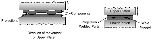
Fig 11.9: Formation of Welds from Projections on Components
Projection welding may be carried out with one projection or more than one projections simultaneously.
No consumables are required in projection welding. It is widely being used for fastening attachments like brackets and nuts etc to sheet metal which may be required in electronic, electrical and domestic equipment.
Production of seam welded Tubes:
Welded tubes are produced by resistance seam welding. Tubes are produced from strips which are wrapped on spool with trimmed edges. The width of strip should be slightly bigger than the periphery of the tube to be produced to take care for the loss of metal in flashout. The strip is fed through set of forming rollers to form first the shape of the tube and then it is passed under the seam welding rolls. Under seam welding rolls the edges are butt welded with some flash out on the joint. This flash out is trimmed and then tubes are cut to required size. The process is shown in Figures 11.10 & 11.11.
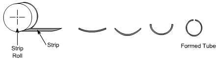
Fig 11.10: Forming of Tube from Strip
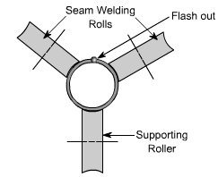
Fig 11.11: Seam Welding of Tube