Lecture 4
Draft or Taper Allowance
By draft is meant the taper provided by the pattern maker on all vertical surfaces of the pattern so that it can be removed from the sand without tearing away the sides of the sand mold and without excessive rapping by the molder. Figure 3 (a) shows a pattern having no draft allowance being removed from the pattern. In this case, till the pattern is completely lifted out, its sides will remain in contact with the walls of the mold, thus tending to break it. Figure 3 (b) is an illustration of a pattern having proper draft allowance. Here, the moment the pattern lifting commences, all of its surfaces are well away from the sand surface. Thus the pattern can be removed without damaging the mold cavity.
Figure 3 (a) Pattern Having No Draft on Vertical Edges
Figure 3 (b) Pattern Having Draft on Vertical Edges
Draft allowance varies with the complexity of the sand job. But in general inner details of the pattern require higher draft than outer surfaces. The amount of draft depends upon the length of the vertical side of the pattern to be extracted; the intricacy of the pattern; the method of molding; and pattern material. Table 2 provides a general guide lines for the draft allowance.
Table 2 : Draft Allowances of Various Metals
|
Pattern material |
Height of the given surface (inch) |
Draft angle (External surface) |
Draft angle (Internal surface) |
|
Wood |
1 1 to 2 2 to 4 4 to 8 8 to 32 |
3.00 1.50 1.00 0.75 0.50 |
3.00 2.50 1.50 1.00 1.00 |
|
Metal and plastic |
1 1 to 2 2 to 4 4 to 8 8 to 32 |
1.50 1.00 0.75 0.50 0.50 |
3.00 2.00 1.00 1.00 0.75 |
Machining or Finish Allowance
The finish and accuracy achieved in sand casting are generally poor and therefore when the casting is functionally required to be of good surface finish or dimensionally accurate, it is generally achieved by subsequent machining. Machining or finish allowances are therefore added in the pattern dimension. The amount of machining allowance to be provided for is affected by the method of molding and casting used viz. hand molding or machine molding, sand casting or metal mold casting. The amount of machining allowance is also affected by the size and shape of the casting; the casting orientation; the metal; and the degree of accuracy and finish required. The machining allowances recommended for different metal is given in Table 3.
Table 3 : Machining Allowances of Various Metals
|
Metal |
Dimension (inch) |
Allowance (inch) |
|
Cast iron |
Up to 12 12 to 20 20 to 40 |
0.12 0.20 0.25 |
|
Cast steel |
Up to 6 6 to 20 20 to 40 |
0.12 0.25 0.30 |
|
Non ferrous |
Up to 8 8 to 12 12 to 40 |
0.09 0.12 0.16 |
Exercise 2
The casting shown is to be made in cast iron using a wooden pattern. Assuming only machining allowance, calculate the dimension of the pattern. All Dimensions are in Inches
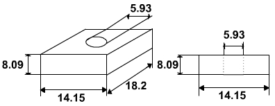
Solution 2
The machining allowance for cast iron for size, up to 12 inch is o.12 inch and from 12 inch to 20 inch is 0.20 inch ( (Table 3)
For dimension 18 inch, allowance = 0.20 inch
For dimension 14 inch, allowance = 0.20 inch
For dimension 8 inch, allowance = 0.12 inch
For dimension 6 inch, allowance = 0.12 inch
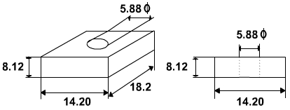
The pattern drawing with required dimension is shown in Figure below
Distortion or Camber Allowance
Sometimes castings get distorted, during solidification, due to their typical shape. For example, if the casting has the form of the letter U, V, T, or L etc. it will tend to contract at the closed end causing the vertical legs to look slightly inclined. This can be prevented by making the legs of the U, V, T, or L shaped pattern converge slightly (inward) so that the casting after distortion will have its sides vertical ( (Figure 4).
The distortion in casting may occur due to internal stresses. These internal stresses are caused on account of unequal cooling of different section of the casting and hindered contraction. Measure taken to prevent the distortion in casting include:
-
Modification of casting design
-
Providing sufficient machining allowance to cover the distortion affect
-
Providing suitable allowance on the pattern, called camber or distortion allowance (inverse reflection)
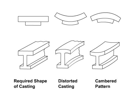
Figure 4: Distortions in Casting
Rapping Allowance
Before the withdrawal from the sand mold, the pattern is rapped all around the vertical faces to enlarge the mold cavity slightly, which facilitate its removal. Since it enlarges the final casting made, it is desirable that the original pattern dimension should be reduced to account for this increase. There is no sure way of quantifying this allowance, since it is highly dependent on the foundry personnel practice involved. It is a negative allowance and is to be applied only to those dimensions that are parallel to the parting plane.
Core and Core Prints
Castings are often required to have holes, recesses, etc. of various sizes and shapes. These impressions can be obtained by using cores. So where coring is required, provision should be made to support the core inside the mold cavity. Core prints are used to serve this purpose. The core print is an added projection on the pattern and it forms a seat in the mold on which the sand core rests during pouring of the mold. The core print must be of adequate size and shape so that it can support the weight of the core during the casting operation. Depending upon the requirement a core can be placed horizontal, vertical and can be hanged inside the mold cavity. A typical job, its pattern and the mold cavity with core and core print is shown in Figure 5.
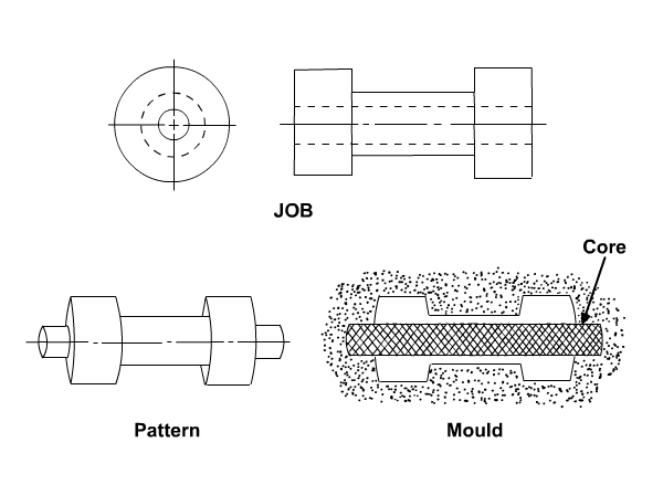
Figure 5: A Typical Job, its Pattern and the Mold Cavity