Validation of present model: some more results
Stress, strain and voltage responses in the sensing coil at the time of delamination have also been predicted and have been displayed in Table 34.2.The expected load at the time of delamination and the delaminating layer are predicted and are listed in the summary of results in Table 34.2. The analysis suggests delamination to be taking place in the second interface from the top in both the cases i.e.12th and 26th layer in 14 and 28 layer composites [see Figures 35.4, 35.5 and 35.6]. It is due to the presence of Terfenol-D particulates in the top layer which has better stiffness and strength properties in comparison to the matrix material and hence, it is in position to sustain greater bending loads. Further, the layer adjacent to the top layer has the fiber orientation in the longitudinal direction and will sustain greater stress in comparison to the third layer in which fibers are in transverse direction and it is likely to delaminate under bending load. It is important to add that if the stacking sequence differs from the present cross ply arrangements, the delamination in a layer will be governed by its fiber orientation and elastic properties. The layer reaching its critical stress value first will be delaminating at the earliest. Figures 34.4, 34.5 and 34.6 show the stress, strain and predicted delamination loads in the present analysis.
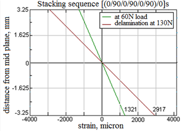
Figure 34.4 Strain across all the interfaces of 14 layer MS-tagged composite at 60 N and 130 N ( i.e. delaminating load )
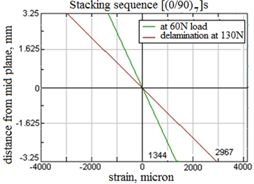
Figure 34.5 Strain across all the interfaces of 28 layer MS-tagged composite at 60 N and 130 N ( i.e. delaminating load)
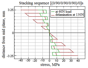
Figure 34.6 Strain across all the interfaces of 28 layer MS-tagged composite at 60 N and 130 N ( i.e. delaminating load)
|