Numerical analysis of woven MS composites
The analysis involves a simply supported beam with a pointed load at the centre which is gradually being increased. The beam is also subjected to an alternating current of the form of Equation (26.3).The description of woven composite used by Guirguitiu et al [2001] is shown in Figure 34.1.
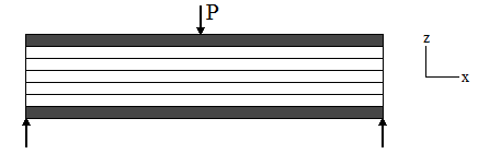
Figure 34.1 Simply supported beam with tagged magnetostrictive particulates in top and bottom layers
Two MS layers at the top and bottom of the beam experience compressive forces N1 and N2. These forces on the beam are statically balanced by other layers with an equivalent and opposite tensile stress, N
Force acting in non- MS layers
 |
(34.1) |
Forces acting on two MS layers

|
|
 |
(34.2) |
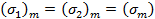
Since the distances from the mid plane and the thickness of the magnetostrictive layers are same
 |
(34.3) |
since,
 |
(34.4) |
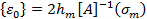
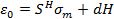
Rearranging for mid plane strain
 |
(34.5) |
It is known from Equation (26.1) that
 |
(34.6) |
Comparing it with Equation (32.13), we get
 |
(34.7) |
Magnetic flux density is governed by the Equation (31.2)
 |
(34.8) |
Hence, the open circuit induced voltage may be calculated from
 |
(34.9) |
Substituting the value of  from Equation (34.5) from Equation (34.5)
 |
(34.10) |
|