Classical laminate theory
In this lecture, the constitutive relationship of a laminated composite beam has been described which will be required to find out the voltage generated in the sensing coil. Consider the laminated beam with ply arrangements as shown in Figure 31.1,
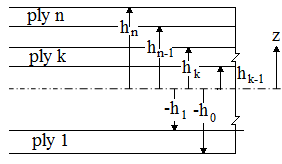
Figure 31.1 Notation for location of ply interfaces of a composite beam
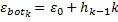
Strain at the top and bottom of  lamina of the composite laminate is given by lamina of the composite laminate is given by
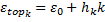 |
(31.1) |
 |
Stresses at the top and bottom interface could be obtained as
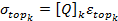 |
(31.2) |
 |
(31.3) |
 is the mid plane strain and is the mid plane strain and  and and  are the distances of lower and upper interfaces of the lamina, are the distances of lower and upper interfaces of the lamina,  is the mid plane curvature and is the mid plane curvature and  is the stiffness matrix. is the stiffness matrix.
The stress resultants are expressed as
 |
(31.4) |
In-plane and bending stress resultants are given by
|
|
 |
(31.5) |
and
 |
(32.6) |
A, B and D are extensional, coupling and bending stiffness matrices. N and M are forces and moments per unit length and h is the total thickness of the laminate beam.
|