Likewise, similar increased voltage responses in elements 4 and 6 are predicted in case of delamination in element 5. Figures 26.3 (a) and (b) show voltage responses for a symmetric pair of elements 1 and 8 for Interface 3. Figures 26.3 (c) and (d) represent another set of symmetric pair of elements 4 and 5. The voltage response in these cases are very similar to the cases discussed earlier.
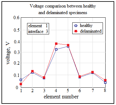
Figure 26.3 (a) Voltage profile for damage in element 1 of interface 3
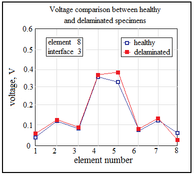
Figure 26.3 (b) Voltage profile for damage in element 8 of interface 3
|