Fans and blowers (Fig. 39.1) are turbomachines which deliver air at a desired high velocity (and accordingly at a high mass flow rate) but at a relatively low static pressure. The pressure rise across a fan is extremely low and is of the order of a few millimeters of water gauge.The upper limit of pressure rise is of the order of 250mm of water gauge.The rise in static pressure across a blower is relatively higher and is more than 1000 mm of water gauge that is required to overcome the pressure losses of the gas during its flow through various passages. A blower may be constructed in multistages for still higher discharge pressure.
Figure 39.1 A centrifugal fan or blower |
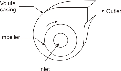
A large number of fans and blowers for relatively high pressure applications are of centrifugal type. The main components of a centrifugal blower are shown in Fig. 39.2. A blower consists of an impeller which has blades fixed between the inner and outer diameters. The impeller can be mounted either directly on the shaft extension of the prime mover or separately on a shaft supported between two additional bearings. Air or gas enters the impeller axially through the inlet nozzle which provides slight acceleration to the air before its entry to the impeller. The action of the impeller swings the gas from a smaller to a larger radius and delivers the gas at a high pressure and velocity to the casing. The flow from the impeller blades is collected by a spiral-shaped casing known as volute casing or spiral casing . The casing can further increase the static pressure of the air and it finally delivers the air to the exit of the blower.
Figure 39.2 Main components of a centrifugal blower |
The centrifugal fan impeller can be fabricated by welding curved or almost straight metal blades to the two side walls (shrouds) of the rotor. The casings are made of sheet metal of different thickness and steel reinforcing ribs on the outside. Suitable sealing devices are used between the shaft and the casing.
A centrifugal fan impeller may have backward swept blades, radial tipped blades or forward swept blades as shown in Fig. 39.3. The inlet and outlet velocity triangles are also shown accordingly in the figure. Under ideal conditions, the directions of the relative velocity vectors  and and  are same as the blade angles at the entry and the exit. A zero whirl at the inlet is assumed which results in a zero angular momentum at the inlet. The backward swept blades are employed for lower pressure and lower flow rates. The radial tipped blades are employed for handling dust-laden air or gas because they are less prone to blockage, dust erosion and failure. The radial-tipped blades in practice are of forward swept type at the inlet as shown in Fig. 39.3. The forward-swept blades are widely used in practice. On account of the forward-swept blade tips at the exit, the whirl component of exit velocity are same as the blade angles at the entry and the exit. A zero whirl at the inlet is assumed which results in a zero angular momentum at the inlet. The backward swept blades are employed for lower pressure and lower flow rates. The radial tipped blades are employed for handling dust-laden air or gas because they are less prone to blockage, dust erosion and failure. The radial-tipped blades in practice are of forward swept type at the inlet as shown in Fig. 39.3. The forward-swept blades are widely used in practice. On account of the forward-swept blade tips at the exit, the whirl component of exit velocity  is large which results in a higher stage pressure rise. is large which results in a higher stage pressure rise.
The following observations may be noted from figure 39.3.
 , if , if  , backward swept blades , backward swept blades
 , if , if  , radial blades , radial blades
 , if , if  , forward swept blades , forward swept blades
| Figure 39.3 Velocity triangles at inlet and outlet of different types of blades of an impeller of a centrifugal blower |
|