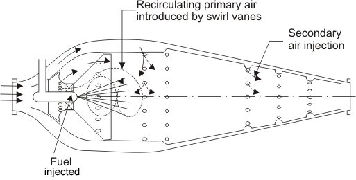
Figure 16.1 Combustion chamber with swirl vanes |
Figure 16.1 indicates the schematic of a combustion chamber. The primary air is introduced through twisted radial vanes known as 'swirl vanes', that results in a vortex motion with a low-pressure region along the axis of the chamber. The fuel is injected in the same direction of air. The vortex motion is some time enhanced by injecting the secondary air through short tangential chutes in the flame tube. The burning gases tends to flow towards the region of low pressure and some portion of them swept round towards the jet of fuel as indicated by the arrow. The objective is to obtain a stable flame.
Aircraft Engines and Propulsion System
The modern aircraft engine have the ability to actuate massive airstream and thus to produce high thrust. The engine airflow rate is perhaps 50 times the fuel flow rate, and the term air breathing engine is quite appropriate. Thus, a continuous stream of air flows through the air-breathing engine. The air is compressed, mixed with fuel, ignited, expanded through a turbine and then expelled as the exhaust gas. The following four types of aircraft engines are generally used
• Turbojet Engine
• Turboprop Engine
• Turbofan Engine
• Ramjet Engine
At low speeds, propeller propulsion is more efficient than jet propulsion. Conventional propellers, however, become inefficient and noisy at flight speeds higher than 0.5 or 0.6 times the speed of sound. In contrast, turbojet and turbofan engines can function efficiently and quietly at flight speeds as high as 0.85 times the speed of sound. Turbojets can also operate at supersonic flight speeds. Ramjet, which is the simplest of all air-breathing engines can operate at a higher speed than turbojet engines and is mostly suitable for supersonic flight. 1. Turbojet Engine
The turbojet engine consists of a gas turbine, the output of which is used solely to provide power to the compressor. The compressor and the turbine are normally mounted on common shaft. Air is taken into the engine through an approximate diffuser duct, passes through the compressor and enters the combustions chamber, where it is mixed and burned with fuel.
Most common fuels are hydrocarbons (Aviation kerosene). The ratio of fuel to air is determined by the maximum allowable gas temperature permitted by the turbine. Normally, a considerable excess air is used. The hot high pressure gases are then expanded through the turbine to a pressure which is higher than the ambient atmosphere, and yet sufficiently lower than the combustion chamber pressure, to produce just enough power in the turbine to run the compressor. After leaving the turbine, the gas is expanded to the ambient pressure through an appropriate nozzle. As this occurs, the gas is accelerated to a velocity, which is greater than the incoming velocity of the ingested air, and therefore produces a propulsive thrust.
|