STAGE EFFICENCY
Despite the development in computational methods to predict the flow field in turbine blade passages, the estimation of stage losses and thus efficiency is still a matter of considerable difficulty. In addition to the primary flow through the blade passage, there are secondary flows which move fluid across the blade passages under the action of centrifugal and coriolis forces; blade loading effects causing incidence and deviation; leakage between the moving blade tip and the stationary shroud; the boundary layers and wakes shed by blades; and for transonic blades, shock waves in the blade passage and at the trailing edges. Another class of effects is the unsteady generated mainly by the interaction of adjacent blade rows. All these contribute to losses.In general, cascade tests of different blade geometries are performed.The results from these cascade tests can be correlated to define the loss coefficients for the stator (nozzle) and rotor blade of turbines.
With reference to the Fig15.1, the effects of loss and thus irreversibility through the stator and rotor are expressed by differences in static enthalpies,  and and  respectively. Non-dimensional "enthalpy loss coefficient" for the nozzle can be defined as, respectively. Non-dimensional "enthalpy loss coefficient" for the nozzle can be defined as,
Similarly, the "enthalpy loss coefficient" for the rotor,
Thus, the expressions for the efficiency can be approximated as:
 |
(15.5) |
 |
(15.6) |
While designing a turbine stage for a particular application, the restriction arises from the view point of blade stress rather than from the aerodynamics to achieve the maximum possible efficiency. In short, the blade speed is limited by the blade stress, particularly in high temperature applications. The turbine designers will often work to a maximum value of blade speed defined by temperature and material properties. Thus in modern times, the turbine blade cooling in very vital, which determines the life of an engine ( particularly for the turbojet engine). In many applications, the characteristics of the compressor which the turbine drives also impose limits on the turbine speed.
Turbine Performance
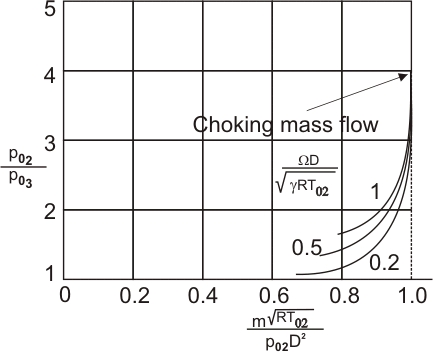
For a given design of turbine operating with a given fluid at sufficiently high Reynolds member, it can be shown from the dimensional analysis as,
where, stagnation states 02 and 03 are at the turbine inlet and outlet, respectively. Figure (15.2) shows the overall performance of a particular single-stage turbine.
Figure15.2 Typical characteristics of a turbine stage |
One can see that pressure ratios greater than those for compressor stages can be obtained with satisfactory efficiency.
The performance of turbines is limited principally by two factors: compressibility and stress. Compressibility limits the mass flow that can pass through a given turbine and, as we will see, stress limits the wheel speed U. The work per stage, for example, depends on the square of the wheel speed. However, the performance of the engine depends very strongly on the maximum temperature. Of course, as the maximum temperature increases, the allowable stress level diminishes; hence in the design of the engine there must be a compromise between maximum temperature and maximum rotor tip speed U.
For given pressure ratio and adiabatic efficiency, the turbine work per unit mass is proportional to the inlet stagnation temperature. Since, in addition, the turbine work in a jet or turboshaft engine is commonly two or three times the useful energy output of the engine, a 1% increase in turbine inlet temperature can produce a 2% or 3% increase in engine output. This considerable advantage has supplied the incentive for the adoption of fairly elaborate methods for cooling the turbine nozzle and rotor blades.
|