Again, combining Eq.14.5 and Eq.14.8, we have
 |
(14.10) |
Which is the expression for R in terms of the exit air angles. For the special case of symmetrical blading ,  and we have and we have  . For the case of . For the case of
 we have we have  . Now for the special case of zero exit swirl, . Now for the special case of zero exit swirl,
 and it follows that and it follows that
 , i.e. , i.e.  and Eq. 14.10 because and Eq. 14.10 because
 |
(14.11) |
Again for zero exit swirl, the blade loading capacity, Eq.13.5 reduces to
 |
(14.12) |
since |
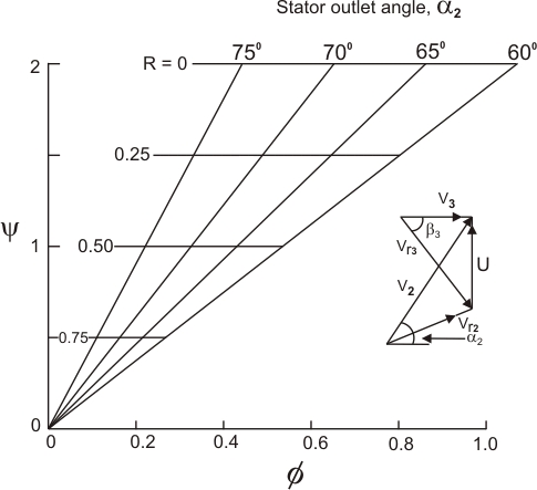
Equations (14.11) and (14.12) have been used in plotting Fig (14.3), which pertains to design conditions only.
Here we see that for a given stator outlet angle, the impulse stage requires a much higher axial velocity ratio than does the 50% reaction stage. In the impulse stage all flow velocities are higher, and that is one reason why its efficiency is lower than that of the 50% reaction stage.
| Figure 14.3 Work capacity Ψ and degree of reaction R of axial turbine stages design for zero exit swirl. |
|