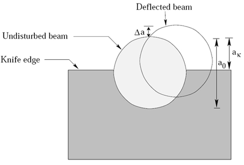
Figure 5.4: View of deflected and undistributed beams at the knife-edge of a schlieren system.
If no disturbance is present, the light beam at the focus of  would be ideally as shown in Figure 5.4, with dimensions would be ideally as shown in Figure 5.4, with dimensions  . These are related to the initial dimensions by the formulas . These are related to the initial dimensions by the formulas

where  and and  are the focal lengths of are the focal lengths of  and , respectively. and , respectively.
In a schlieren system, the knife edge kept at the focal length of the second concave mirror is first adjusted, when no disturbance in the test region is present, to cut off all but an amount correnponding to the dimension  of the light beam Let of the light beam Let  be the original size of the laser beam.If the knife edge is properly positioned, the illumination at the screen uniformaly changes depending upon its direction of the movement. Let be the original size of the laser beam.If the knife edge is properly positioned, the illumination at the screen uniformaly changes depending upon its direction of the movement. Let  be the be the illumination at the screen when no knife-edge is present. The illumination be the be the illumination at the screen when no knife-edge is present. The illumination  with the knife-edge inserted in the focal plane of the of the second concave mirror but without any disturbance in the test region will be given by with the knife-edge inserted in the focal plane of the of the second concave mirror but without any disturbance in the test region will be given by
Let  be the deflection of the light beam in the vertical direction be the deflection of the light beam in the vertical direction  above the knife edge corresponding to the angular deflection ( above the knife edge corresponding to the angular deflection ( ) of the beam after the test region experiences a change in the refractive index. Then from Figure 5.4, can be expressed as ) of the beam after the test region experiences a change in the refractive index. Then from Figure 5.4, can be expressed as
where the sign is determined by the direction of the displacement of the laser beam in the vertical direction; it is positive when the shift is in the upward direction and negative if the laser beam gets deflected below the level of the knife-edge. In the present discussion, the gradients in the fluid layer are in the upward direction and only the positive sign in Equation 5 is considered.
|

