Steady state
Results are presented below for three Rayleigh number namely  , and corresponding to cavity sizes of 4.0, 5.0, and 5.7 cm respectively. Figure 4.43 (a) shows the overall distribution of fringes in the full cavity at steady state attained with a Rayleigh number of , and corresponding to cavity sizes of 4.0, 5.0, and 5.7 cm respectively. Figure 4.43 (a) shows the overall distribution of fringes in the full cavity at steady state attained with a Rayleigh number of  . The spacing among fringes near the wall is seen to be small around the midplane of the cavity and gradually increases towards its edges. Since each fringe is an isotherm a small fringe spacing gives rise to a large local heat flux. The largest local heat flux on the cavity walls at steady state occurs around the midplane of the cavity. The fluid accelerates on one side of the midplane, reaches a maximum at this point, and decelerates to small values on the other side of the cavity, as it approaches the side walls. The overall flow pattern in the cavity is hence unicellular. . The spacing among fringes near the wall is seen to be small around the midplane of the cavity and gradually increases towards its edges. Since each fringe is an isotherm a small fringe spacing gives rise to a large local heat flux. The largest local heat flux on the cavity walls at steady state occurs around the midplane of the cavity. The fluid accelerates on one side of the midplane, reaches a maximum at this point, and decelerates to small values on the other side of the cavity, as it approaches the side walls. The overall flow pattern in the cavity is hence unicellular.
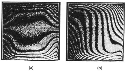
Figure 4.43: (a) Fringe patterns at steady state in a square cavity; (b) wedge fringes at steady state in a square cavity 
Figure 4.43 (b) shows wedge fringes in the cavity at steady state at the same Rayleigh number of . The wedge fringes are obtained by deliberately misaligning the mirrors of the interferometer so that under zero flow conditions a set of parallel fringes are seen. When temperature gradients are present in the test cell the fringes are curved and the fringe slope is a measure of the local heat flux. The direction in which the fringes are displaced depends on the direction to the local fluid velocity. Figure 4.43 (b) shows that the fringes are displaced to the right near the bottom wall and to the left near the top wall. This confirms the result from the infinite fringe setting (fig.4.43 (a) that the flow in the cavity is unicellular with roll moving in an anticlockwise direction.
|