As an example of the interference phenomena, consider the formation of fringes in
the arrangement shown in Figure 4.4. A transparent block A rests on another block B
and the spacing d between them varies with position. Surface 2 is partly silvered and
surface 3 is fully silvered and these surfaces are exposed to light at normal incidence. The
interference pattern arising from the superposition of rays a (leaving A after reflection)
and and b (leaving B after reflection) is shown in Figure 4.4. The pattern see in Figure
4.4 is an interference pattern of wedge fringes since they originate from a wedge-shaped
alI gap.
If the incident light has a phase angle  then then  and and
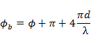
Here, the phase difference arising from the block A can be ignored because its contribution
is common to both rays  and and  . Hence . Hence
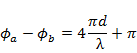
When  the phase difference between the two light beams is the phase difference between the two light beams is  and the first line
of the interference pattern is a dark line rising from destructive interference. As we go
from the and the first line
of the interference pattern is a dark line rising from destructive interference. As we go
from the  to to  fringe fringe  changes from and so changes from and so 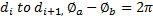

The factor  is related to the fact that ray traverses the distance twice. The above
method permits measurement of starting from the first dark fringe where . is related to the fact that ray traverses the distance twice. The above
method permits measurement of starting from the first dark fringe where .
Fringes will follow lines of constant and hence represent contour lines on an uneven
surface. This method can be used to measure or the flatness of a surface, the latter
being related to the straightness of the wedge fringes (Figure 4.4).
|