Flow in the test section was set up by a small fan driven by a single phase motor. The suction side of the fan was used to draw the flow from the test cell.
The power supply to the blower was from an online uninterrupted power supply unit to ensure practically constant input voltage to the motor.
For better control of
the voltage setting, particularly at low fan RPM and hence at low flow rates, the output
of the UPS was stepped down via two variacs connected in series. In turn, this had
the effect of minimizing the velocity fluctuations in the approach flow. The free stream
turbulence level in the approach flow was quite small and it was found to be less than the background noise of the anemometer (  %). Flow parallelism in the approach ow was better than %). Flow parallelism in the approach ow was better than  over over  of the width of the test cell. The validation of the
test cell is discussed in a later section of the present module. of the width of the test cell. The validation of the
test cell is discussed in a later section of the present module.
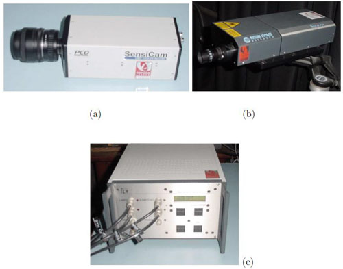
Fig 3.10: PIV components: (a) CCD Camera (b) Nd-YAG laser (c) Synchronizer
|