| |
Experimental Setup
A schematic drawing of the experimental setup is shown in Figure 3.8. It comprises
the following components: flow circuit, traversing mechanism for hotwire measurements,
laser (pulsed), CCD camera, seeding
arrangement for PIV measurements, and data acquisition
system. The free-stream velocity approaching
the cylinder has been determined
using a pitot-static tube connected to a micro-manometer. The
micro-manometer has a
resolution of 0:001 mm of  it translates to an error in Reynolds number of
about it translates to an error in Reynolds number of
about  The details of the test cell are discussed here and the PIV and HWA
techniques are presented in the following section. The details of the test cell are discussed here and the PIV and HWA
techniques are presented in the following section.
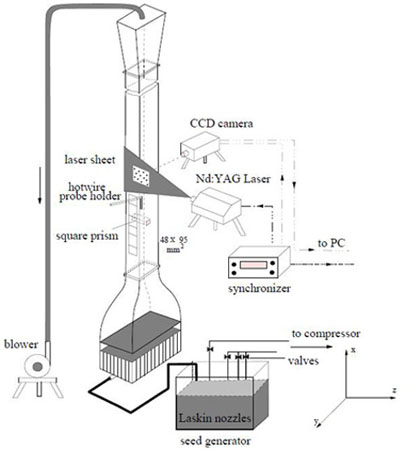
Fig 3.8: Schematic of the experimental setup
|