FUEL CELL
Working Principle
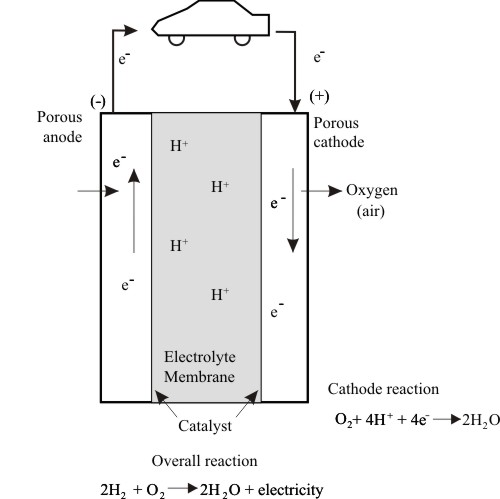
Fuel cell was invented in 1839 by Sir William Groves. It is an electro-chemical device, which continuously converts the chemical energy of fuel directly to electricity. The working principle of H2-O2 fuel cell is shown on Fig. 7.15.
- The fuel-cell has two electrodes made of porous material coated with platinum as catalyst.
- The electrodes are separated by a solid semi-permeable electrolyte.
- Hydrogen flows into fuel cell on catalytic anode and gives up an electron.
- Negatively charged oxygen at cathode attracts hydrogen protons through the solid electrolyte membrane. On cathode, hydrogen and oxygen ions combine to produce water.
- The electrons flow through external circuit producing current.
| Figure 7.15 |
Schematic of H2 – O2 fuel cell. |
Fuel Cell Power Output
Open circuit standard EMF of fuel cell at reference condition is given by
 |
(7.1) |
where:
 = Gibbs free energy of formation for the reaction at reference condition of 298 K, and 1 atm = Gibbs free energy of formation for the reaction at reference condition of 298 K, and 1 atm
n = no. of electrons per molecule of fuel e.g. for H2 -O2 fuel cell n = 2
F = Faraday constant = 96,485 Coulombs/ electron mol.
At the other operating conditions, EMF of the fuel cell is,
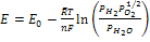 |
(7.2) |
where PH2, PO2, PH2O are the partial pressures in atm.
Fuel cells can also use and operate directly on other fuels like methanol and methane Theoretical EMF of some fuel cell systems is given in Table 7.3
Table 7.3 |
Theoretical EMF for Some Fuel Cells at reference conditions |
| Fuel |
Reaction |
n |
E0 , V |
H2 |
H2 + 0.5 O2 → H2 O |
2 |
1.229 |
| Methane |
CH4+ 2O2 → CO2+2H2O(l) |
8 |
1.006 |
| Methanol |
CH3 OH (l)+ 1.5O2 → CO2+2H2O (l) |
6 |
1.214 |
Actual cell voltage is lower and is about 50 to 60% only of the theoretical EMF due to;
- Slow rate of chemical reactions
- Internal cell resistance
- As the current drawn is increased beyond about 0.7 A/cm2, the concentration polarization causes a further voltage drop.
Typical fuel cell characteristics are shown on Fig. 7.16. The change in current and voltage efficiencies versus current drawn from the fuel cell are shown.
|