contd...
Common Rail Diesel Injection (CRDI) Systems
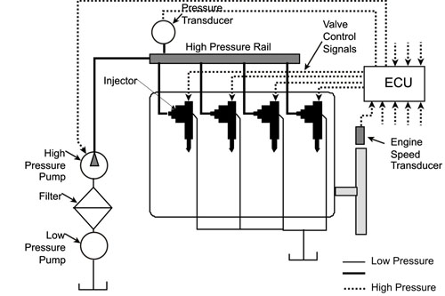
In the common rail systems, the high fuel pressure is generated by a common pump that is separate from the injectors. The fuel pressure is independent of engine speed and load. A typical layout of the common rail systems is shown in Fig. 6.6.The CRDI has four main components;
(i) high-pressure pump
(ii) high-pressure distribution rail (common rail) and pipes
(iii) injectors, and
(iv) Electronic engine control unit (ECU).
A mechanical pump raises the fuel pressure and feeds the common rail with fuel at high pressure. The common rail is connected to the injectors by short pipes. A solenoid valve in each injector controls the injection timing and quantity.
| Figure 6.6 |
Schematic layout of a common rail diesel injection system |
In one design of the common rail systems, the rail pressure is same as the injection pressure. In another design known as ‘intensified’ CRDI system, the fuel pressure in rail is lower and it is multiplied by a factor of 3:1 to 10:1 in the injector body by a stepped piston to raise it to the injection pressure. The CRDI systems mostly operate at pressures of around 1600 bars.
The injection pressure characteristics of the CRDI, EUI and inline pump- nozzle systems are compared in Fig 6.7. The main advantage of the common rail system over the conventional in-line jerk pumps is that injection pressure is constant and independent of engine speed and load. For inline pump- nozzle systems, the injection pressure is quite
|