OVERVIEW OF CAD/CAM CAD if often defined
in a variety of ways and includes a large range of activities. Very broadly it
can be said to be the integration of computer science (or software) techniques in engineering design.
At one end when we talk of modeling, iIt encompasses the following: Use of computers (hardware & software) for designing products Numerical method, optimizations etc. 2D/3D drafting 3D modeling for visualization Modeling curves, surfaces, solids, mechanism, assemblies, etc. The models thus developed are first visualized on display
monitors using avariety of techniques including wire frame displa, shaded image
display, hidden surface removed display and so on. Once the designer is
satisfied, these models are then used for various types of analysis /
applications. thus, at the other end it includes a number of analysis
activities. These could be: Stress (or deflection) analysis, i.e. numerical methods
meant for estimating the behaviour of an artifact with respect to these
parameters. It includes tools like the Finite Element Method (FEM). Simulation of actual use Optimization Other applications like
CAD/CAM integration Process planning These are activities which normally use models developed
using one or more of the techniques mentioned above. These activities are often
included in other umbrellas like CAM or CAE. A term often used is CAx to include
this broad set of activities. They all use CAD models and often the kind of
application they have to be used ina determines the kind of amodel to be
developed. Hence, in this course I cover them under the umbrella of CAD.
In this course we will strive to give an overview of modelling techniques
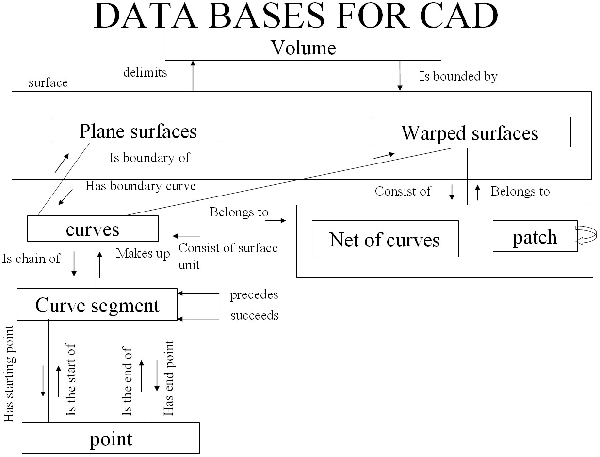
followed by some applications, specifically CAM. Thus there are three aspects to CAD. Modelling typically includes a set of activities like The figure below explains what a typical CAD model
would need to define, what kind of entities need to be defined and what
relationships exist between them.
At
the highest level we have the volume which is defined by (or "delimited by") a
set of surfaces. These surfaces can be either planar or curved / warped. A
planar surface can be bounded by a set of curves. A curved surface can be seen
as a net of curves. These curves are typically a succession of curve segemnts
which define the complete the curve. The curve segment is defined using a set of
end points / control points which govern the nature of the curve. Thus a
relation ship is defined between entities at each level. Once such a relationship is defined, a geometric model of the artifact is
available. In any design there might be manysuch artifacts. One then has to
define properties of each of these artifacts and define a relationship between
them. The properties and the relationships needed are dependant on the
application the model is to be used for subsequently. But one common application
that all models have to go through is visualization of the model (s).
DISPLAY / VISUALIZATION Displaying the model requires the following: Once a model is visualized on the screen and approved by the conceptual
designer, it has to go through a number of analysis. Some of the kinds of usage
this model might have to go through are the following: Having given the overview of the kind of activties that can come under the
umbrella of CAD the uses these CAD models can be put to, I know highlight what
aspects of these would be covered in this course. Needless to say, all these
activities would be well beyond the scope of one single course. Therefore this
course, which is targeted to give an overview of CAD and its applications would
include the following:
What is CAD?
MODELING