... Contd from previous slide...Load Flow Results
Consider the line segment 1-2. The voltage of bus-1 is V1 = 1.05 < 0° per unit while that of bus-2 is V2 = 0.9826 < − 5.0124° per unit. From (4.52) we then have
 per unit per unit |
|
Therefore the complex power dispatched from bus-1 is
where the negative signal indicates the power is leaving bus-1. The complex power received at bus-2 is
 MW MW |
|
Therefore out of a total amount of 101.0395 MW of real power is dispatched from bus-1 over the line segment 1-2, 98.6494 MW reaches bus-2. This indicates that the drop in the line segment is 2.3901 MW. Note that
 MW MW |
|
where R12 is resistance of the line segment 1-2. Therefore we can also use this method to calculate the line loss.
Now the reactive drop in the line segment 1-2 is
 MV Ar MV Ar |
|
We also get this quantity by subtracting the reactive power absorbed by bus-2 from that supplied by bus-1. The above calculation however does not include the line charging. Note that since the line is modeled by an equivalent- p , the voltage across the shunt capacitor is the bus voltage to which the shunt capacitor is connected. Therefore the current I 12 flowing through line segment is not the current leaving bus-1 or entering bus-2 - it is the current flowing in between the two charging capacitors. Since the shunt branches are purely reactive, the real power flow does not get affected by the charging capacitors. Each charging capacitor is assumed to inject a reactive power that is the product of the half line charging admittance and square of the magnitude of the voltage of that at bus. The half line charging admittance of this line is 0.03. Therefore line charging capacitor will inject
 MV Ar MV Ar |
|
at bus-1. Similarly the reactive injected at bus-2 will be
 MV Ar MV Ar |
|
The power flow through the line segments 1-2 and 1-5 are shown in Fig. 4.2.
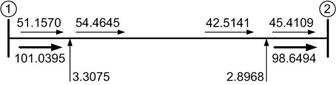
(a)
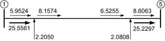
(b)
Fig. 4.2 Real and reactive power flow through (a) line segment 1-2 and (b) line segment 1-5. The thin lines indicate reactive power flow while the thick lines indicate real power flow.
|
