An Alternate Method of Voltage Injection
So far we have assumed that the series compensator injects a voltage that is in quadrature with the line current and its magnitude is proportional to the magnitude of the line current. A set of very interesting equations can be obtained if the last assumption about the magnitude is relaxed. The injected voltage is then given by
 |
(10.26) |
We can then write the above equation as
 |
(10.27) |
i.e., the voltage source in quadrature with the current is represented as a pure reactance that is either inductive or capacitive. Since in this form we injected a constant voltage in quadrature with the line current, we shall refer this as constant voltage injection mode. The total equivalent inductance of the line is then
Defining VS = V < δ and VR < 0° , we can then write the power transfer equation as
Since | VQ | / | IS | = XQ , we can modify the above equation as
 |
(10.28) |
Consider the phasor diagram of Fig. 10.14 (a), which is for capacitive operation of the series compensator. From this diagram we get
Similarly from the inductive operation phasor diagram shown in Fig. 10.14 (b), we get
Substituting the above two equations in (10.28) and rearranging we get
 |
(10.29) |
where the positive sign is for capacitive operation.
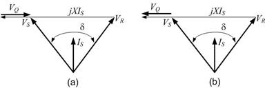
Fig. 10.14 Phasor diagram of series compensated system: (a) capacitive operation and (b) inductive operation.
| 


