Transposed Line
The inductances that are given in (1.36) to (1.38) are undesirable as they result in an unbalanced circuit configuration. One way of restoring the balanced nature of the circuit is to exchange the positions of the conductors at regular intervals. This is called transposition of line and is shown in Fig.1.8. In this each segment of the line is divided into three equal sub-segments. The conductors of each of the phases a, b and c are exchanged after every sub-segment such that each of them is placed in each of the three positions once in the entire segment. For example, the conductor of the phase-a occupies positions in the sequence 1, 2 and 3 in the three sub-segments while that of the phase-b occupies 2, 3 and 1. The transmission line consists of several such segments.
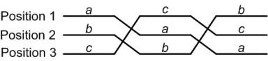
Fig. 1.8 A segment of a transposed line.
In a transposed line, each phase takes all the three positions. The per phase inductance is the average value of the three inductances calculated in (1.36) to (1.38). We therefore have
 |
(1.39) |
This implies
From (1.35) we have a + a2 = - 1. Substituting this in the above equation we get
 |
(1.40) |
The above equation can be simplified as
 |
(1.41) |
Defining the geometric mean distance ( GMD ) as
 |
(1.42) |
equation (1.41) can be rewritten as
 H/m H/m |
(1.43) |
Notice that (1.43) is of the same form as (1.30) for symmetrically spaced conductors. Comparing these two equations we can conclude that GMD can be construed as the equivalent conductor spacing. The GMD is the cube root of the product of conductor spacings. |